1. Product Overview
The KUAIQU SPPS-K3010 is a high-precision variable DC power supply designed for laboratory, R&D, and industrial applications. It features a 5-digit TFT color display, offering both numerical and graphical (curve) representations of output voltage and current. This unit provides precise control over voltage (0-30V) and current (0-10A) with microampere-level resolution (0.01mA), ensuring accurate power delivery for sensitive electronic equipment.
Key features include advanced safety protections (Over-Voltage Protection - OVP, Over-Current Protection - OCP, Short-Circuit Protection - SCP), a memory function for storing and recalling up to four sets of parameters, and a user-friendly lock function to prevent accidental adjustments. It also incorporates USB-A and USB-C charging ports for convenience and an intelligent temperature-controlled cooling fan for stable, quiet operation.

Figure 1.1: Front view of the KUAIQU SPPS-K3010 DC Power Supply, showcasing its compact design and clear display.
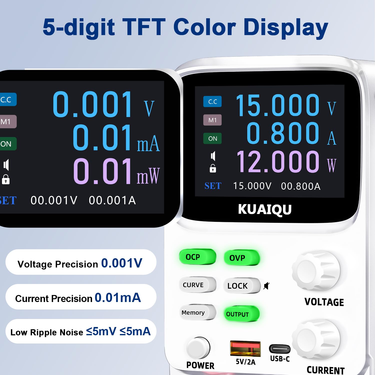
Figure 1.2: The 5-digit TFT color display provides high-precision readings, including 0.001V voltage precision and 0.01mA current precision.
2. Safety Instructions
To ensure safe operation and prolong the lifespan of your device, please read and adhere to the following safety guidelines:
- Always connect the power supply to a grounded electrical outlet.
- Do not operate the device in wet or damp conditions.
- Ensure proper ventilation around the unit to prevent overheating. Do not block ventilation openings.
- Avoid applying voltage or current exceeding the specified maximum ratings.
- Before making any connections or disconnections, ensure the output is turned off and the power supply is disconnected from the main power source.
- Do not open the casing of the power supply. There are no user-serviceable parts inside. Refer all servicing to qualified personnel.
- Keep the device away from flammable materials and explosive gases.
- Use only the provided power cable and output cables.
3. Product Components
Familiarize yourself with the various components and controls of your KUAIQU SPPS-K3010 DC Power Supply.

Figure 3.1: Front Panel Overview. This image displays the front panel of the power supply, highlighting the TFT display, control buttons (OCP, OVP, CURVE, LOCK, Memory, OUTPUT), rotary encoder knobs for Voltage and Current, Power button, USB-A and USB-C charging ports, and output terminals (+, -, GND).
3.1 Front Panel Controls and Indicators
- TFT Color Display: Shows voltage, current, power, and curve displays.
- OCP Button: Over-Current Protection setting and activation.
- OVP Button: Over-Voltage Protection setting and activation.
- CURVE Button: Toggles the real-time voltage and current curve display.
- LOCK Button: Locks/unlocks the control panel to prevent accidental changes.
- Memory Button: Accesses and saves preset voltage/current values (M1-M4).
- OUTPUT Button: Enables or disables the power output.
- VOLTAGE Knob: Rotary encoder for adjusting output voltage. Press to switch digit selection.
- CURRENT Knob: Rotary encoder for adjusting output current. Press to switch digit selection.
- POWER Button: Main power switch for the unit.
- USB-A / USB-C Ports: For charging external electronic devices.
- Output Terminals (+, -, GND): Connect positive, negative, and ground leads to the load.
3.2 Rear Panel
The rear panel typically includes the AC power input socket, a fuse holder, and the cooling fan exhaust.
4. Setup
4.1 Unpacking and Inspection
- Carefully remove the power supply and all accessories from the packaging.
- Verify that all items listed in the "What's in the Box" section are present: 1x DC power supply, 1x output power cord, 1x power cord, 1x user manual.
- Inspect the unit for any signs of physical damage. If damage is found, contact your supplier immediately.
4.2 Power Connection
- Ensure the power supply's main power switch is in the OFF position.
- Connect the provided AC power cord to the power input socket on the rear panel of the power supply.
- Plug the other end of the AC power cord into a grounded electrical outlet (110V AC).
4.3 Connecting the Load
- Ensure the power supply's output is OFF (the OUTPUT button LED should be off).
- Connect the red output cable to the positive (+) terminal and the black output cable to the negative (-) terminal on the front panel.
- Connect the other ends of the output cables to your load device, ensuring correct polarity. For safety, connect the green ground (GND) terminal to the chassis of your load if required.
5. Operating Instructions
5.1 Powering On and Off
- To power on, press the POWER button. The display will illuminate.
- To power off, press the POWER button again.
5.2 Adjusting Voltage and Current

Figure 5.1: Precision adjustment using encoder knobs. This image illustrates how to use the rotary encoder knobs for precise voltage and current adjustments, showing the process of pressing the knob to select digits and rotating to change values.
- Select Parameter: Rotate the VOLTAGE or CURRENT knob to highlight the desired parameter on the display.
- Select Digit: Press the VOLTAGE or CURRENT knob to move the cursor to the digit you wish to adjust. Repeated presses cycle through the digits.
- Adjust Value: Rotate the knob to increase or decrease the value of the selected digit.
- Confirm: Once the desired value is set, stop rotating. The value will be applied.
5.3 Enabling/Disabling Output
After setting the desired voltage and current, press the OUTPUT button to enable the power output to your load. The LED on the button will illuminate. Press it again to disable the output.
5.4 Memory Function (4 Groups of Storage)

Figure 5.2: Intelligent 4-group data storage. This image details the steps for using the memory function to store and recall up to four sets of voltage and current parameters (M1-M4).
- Enter Settings: Press the Memory button.
- Select Memory Slot: Rotate the VOLTAGE knob to select a memory slot (M1-M4).
- Set Values: Long press the VOLTAGE knob to enter setting mode. Short press and rotate the VOLTAGE/CURRENT knobs to set the desired voltage and current values for the selected slot.
- Save Settings: Long press the VOLTAGE knob again to save the settings to the chosen memory slot.
- Recall Settings: To use a saved setting, rotate and short press the VOLTAGE knob to select the desired memory group (M1-M4) and then short press it again to apply.
5.5 Curve Display and Battery Simulation

Figure 5.3: Curve display and battery simulation. This image shows the real-time voltage and current curve display, useful for observing output stability and for applications like battery simulation and testing standby power consumption.
Press the CURVE button to toggle the real-time voltage and current curve display. This feature allows for visual monitoring of output stability and transient behavior, which is particularly useful for tasks such as battery simulation and testing standby power consumption.
5.6 Intelligent A/mA Conversion
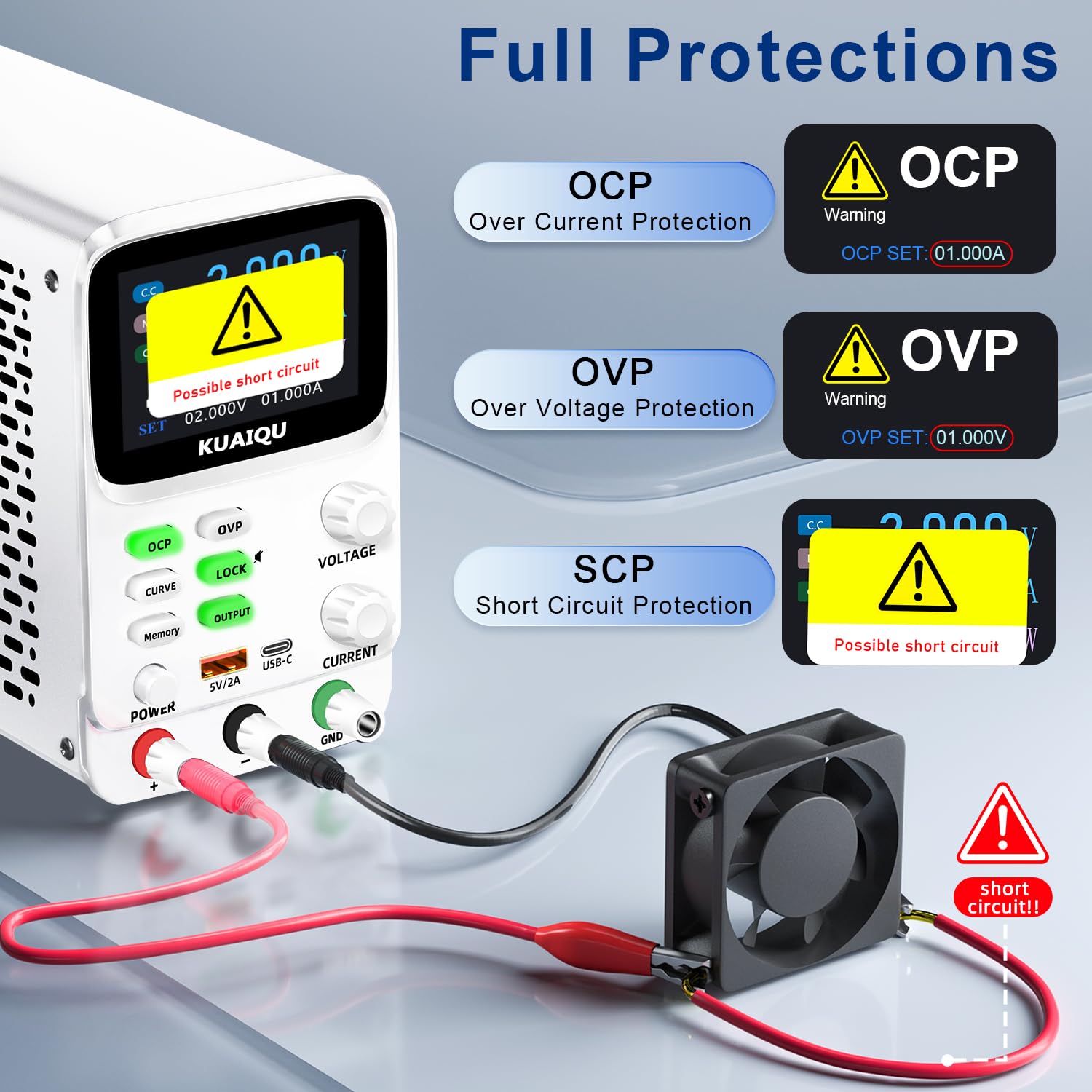
Figure 5.4: Intelligent A/mA Conversion. The display automatically switches to milliampere (mA) readings when the current value drops below 0.1A, providing enhanced precision for low-current applications.
The power supply automatically switches its current display from Amperes (A) to milliamperes (mA) when the output current drops below 0.1A. This intelligent conversion ensures optimal readability and precision for microampere-level measurements.
5.7 Protection Functions (OVP, OCP, SCP)
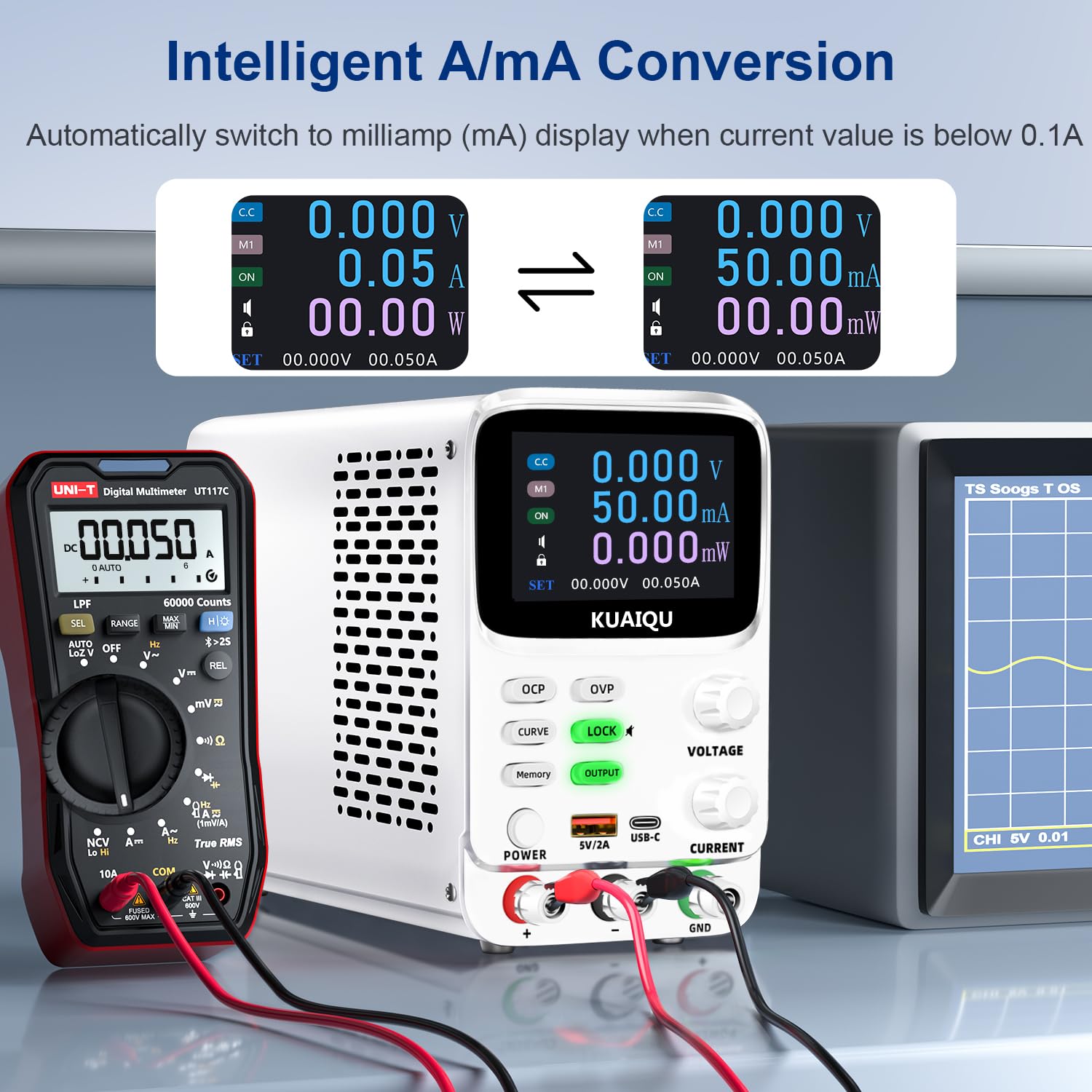
Figure 5.5: Full protection alarms. This image illustrates the Over-Current Protection (OCP), Over-Voltage Protection (OVP), and Short-Circuit Protection (SCP) features, showing how the device alerts and cuts off power when limits are exceeded or a short circuit is detected.
The power supply includes built-in protection mechanisms:
- Over-Voltage Protection (OVP): Prevents output voltage from exceeding a preset limit.
- Over-Current Protection (OCP): Prevents output current from exceeding a preset limit.
- Short-Circuit Protection (SCP): Automatically cuts off output in case of a short circuit.
To set OVP/OCP limits:
- Long press the OVP or OCP button to enter setting mode.
- Use the VOLTAGE or CURRENT knob to adjust the protection limit.
- Short press the OVP or OCP button again to save the setting.
If a protection is triggered, the output will be cut off, and an alarm will be displayed (e.g., "OVP", "OCP", or "Possible short circuit"). Address the issue and then press the OUTPUT button to re-enable output.
5.8 Lock Function
Press the LOCK button to lock the control panel, preventing accidental changes to settings. The lock icon will appear on the display. Press it again to unlock. Long pressing the LOCK button will toggle the encoder knob adjustment beeping sound.
5.9 USB Charging Ports
The front panel includes USB-A and USB-C ports (5V/2A) for convenient charging of compatible electronic devices. These ports operate independently of the main power output settings.
6. Maintenance
6.1 Cleaning
- Before cleaning, ensure the power supply is turned off and disconnected from the main power source.
- Use a soft, dry cloth to wipe the exterior of the unit.
- Do not use abrasive cleaners, solvents, or harsh chemicals.
- Periodically check the ventilation openings for dust accumulation and clean gently with a soft brush or compressed air.
6.2 Storage
- Store the power supply in a cool, dry environment, away from direct sunlight and extreme temperatures.
- Keep it away from dust and moisture.
- If storing for an extended period, it is recommended to place it back in its original packaging.
7. Troubleshooting
This section addresses common issues you might encounter. If the problem persists, please contact customer support.
7.1 No Power / Display Off
- Check Power Cable: Ensure the AC power cable is securely connected to both the power supply and the wall outlet.
- Check Wall Outlet: Verify that the wall outlet is functional by plugging in another device.
- Check Power Switch: Ensure the main POWER button on the front panel is pressed.
- Check Fuse: The fuse located on the rear panel might be blown. Replace it with a fuse of the same type and rating (refer to specifications).
7.2 No Output Voltage/Current
- Check OUTPUT Button: Ensure the OUTPUT button is pressed and its LED is illuminated.
- Check Connections: Verify that the output cables are correctly and securely connected to both the power supply and the load.
- Check OVP/OCP: If OVP or OCP is triggered, the output will be disabled. Check the display for "OVP" or "OCP" warnings. Adjust the voltage/current settings or protection limits as needed, then press OUTPUT to re-enable.
- Check Short Circuit: If "Possible short circuit" is displayed, disconnect the load and check for any short circuits in your circuit.
- Voltage/Current Settings: Ensure the set voltage and current values are not zero.
7.3 Display Issues
- No Display: Refer to "No Power / Display Off" section.
- Incorrect Readings: Ensure proper connections and calibration. If readings are consistently inaccurate, contact support.
8. Specifications
| Feature | Specification |
|---|---|
| Model Name | SPPS-K3010 |
| Brand | KUAIQU |
| Output Voltage Range | 0-30V |
| Output Current Range | 0-10A |
| Output Wattage | 300 Watts |
| Voltage Resolution | 0.001V (1mV) |
| Current Resolution | 0.01mA (10µA) |
| Display | 2.8-inch TFT Color LCD (5-digit) |
| Protection Features | OVP (Over-Voltage Protection), OCP (Over-Current Protection), SCP (Short-Circuit Protection) |
| Memory Storage | 4 groups of editable parameters |
| USB Charging Ports | USB-A, USB-C (5V/2A) |
| Cooling Method | Intelligent temperature-controlled cooling fan |
| Product Dimensions (L x W x H) | 7.6 x 3.4 x 5.5 inches |
| Item Weight | 2.5 Pounds |
| UPC | 768351108799 |
9. Warranty and Customer Support
KUAIQU is committed to providing high-quality products and excellent customer service. This product undergoes thorough inspection before shipment to ensure its quality.
- Quality Assurance: All KUAIQU lab power supplies and accessories are inspected to ensure good quality upon receipt.
- Technical Support: If you have any questions regarding the operation, troubleshooting, or any other aspect of your KUAIQU SPPS-K3010 DC Power Supply, please do not hesitate to contact our customer service team.
- Contact Information: Refer to the contact details provided with your purchase or visit the official KUAIQU website for support.


