
1. Introduction
This manual provides essential instructions for the safe and effective use of your Hasweld 250A 10ft Heavy-Duty MIG Welding Gun. Please read this manual thoroughly before installation, operation, or maintenance to ensure proper function and safety.
The Hasweld 250A 10ft Heavy-Duty MIG Welding Gun is designed for compatibility with various Lincoln wire feeders, including LN-7, LN-8, LN-9, LN-25, LN-25PRO, LF-72, LF-74, LN415, LN742, and SYNERGIC 7 Power 25M. It is rated for 250A operation and features a 10-foot cable length.

Image 1.1: Overview of the Hasweld 250A 10ft Heavy-Duty MIG Welding Gun, showing the handle, cable, and connection points.
Package Contents:
- One 10ft Heavy-Duty MIG Welding Gun (250A)
- One Nozzle (Tweco #2 parts 22-50 compatible)
- One Insulator (Tweco #2 parts 32 compatible)
- One Gas Diffuser (Tweco #2 parts 52 compatible)
- Ten Contact Tips (Tweco #2 parts 14 Series compatible)
2. Safety Information
Welding operations involve significant risks. Always adhere to national and local safety regulations. Failure to follow safety precautions can result in serious injury or death.
General Safety Precautions:
- Electric Shock Can Kill: Ensure proper grounding. Do not touch live electrical parts. Wear dry insulating gloves and protective clothing.
- Fumes and Gases Can Be Hazardous: Keep your head out of the fumes. Use ventilation or exhaust to remove fumes from the breathing zone.
- Arc Rays Can Burn Eyes and Skin: Wear a welding helmet with a proper shade filter. Wear appropriate protective clothing to protect skin.
- Fire and Explosion Hazard: Remove all flammables from the welding area. Have a fire extinguisher readily available.
- Hot Parts Can Cause Severe Burns: Allow equipment to cool before touching. Wear insulated gloves.
- Magnetic Fields: Pacemaker wearers should consult their doctor before welding.
3. Setup Instructions
Proper setup is crucial for safe and efficient welding. Follow these steps carefully.
3.1 Connecting the Welding Gun
- Power Off: Ensure your welding machine and wire feeder are completely powered off and disconnected from the main power supply.
- Connect Control Cable: Locate the control cable connector on the welding gun (Image 3.1) and align it with the corresponding receptacle on your wire feeder. Push firmly until it clicks into place.
- Connect Gas Inlet: Attach the brass gas inlet fitting (Image 3.2) on the welding gun to the gas output port on your wire feeder or welding machine. Ensure a tight seal to prevent gas leaks.
- Secure Power Connection: Connect the main power cable of the welding gun to the appropriate power terminal on your welding machine. Refer to your welding machine's manual for specific connection points.
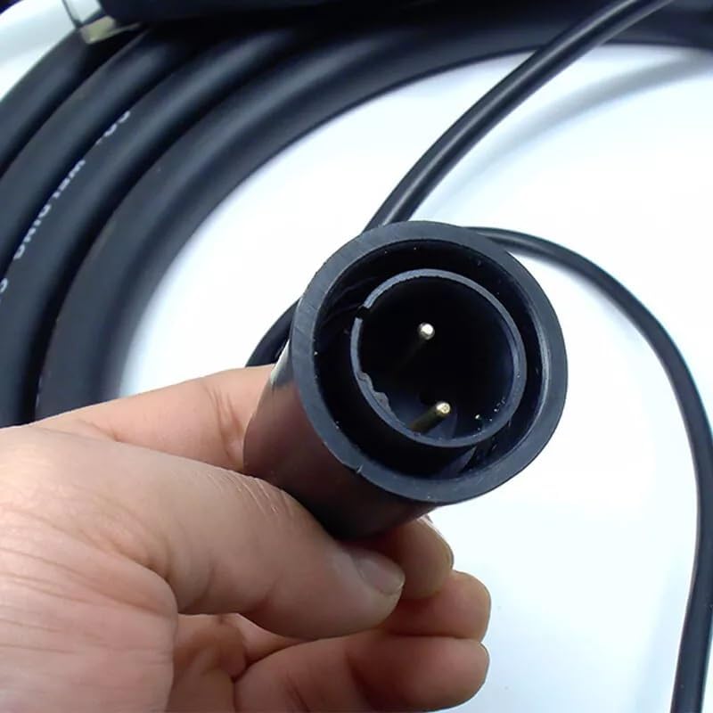
Image 3.1: Close-up of the welding gun's control cable connector, showing the two pins for electrical connection.

Image 3.2: Close-up of the brass gas inlet fitting on the welding gun, designed for secure gas line connection.
3.2 Installing Consumables
- Install Contact Tip: Screw the appropriate contact tip (matching your wire diameter) into the diffuser.
- Install Gas Diffuser: Place the gas diffuser over the contact tip and secure it.
- Install Insulator: Slide the insulator over the diffuser.
- Install Nozzle: Push or screw the nozzle onto the gun neck, ensuring it is seated correctly.
4. Operating Instructions
Once the welding gun is properly set up, you can begin operation. Always wear appropriate personal protective equipment (PPE).
4.1 Wire Feeding
- Load Wire: Ensure the correct welding wire is loaded into your wire feeder.
- Feed Wire: With the welding gun pointed away from yourself and others, press the trigger to feed the wire through the gun. Adjust wire feed speed on your welding machine as needed.
4.2 Gas Flow
- Open Gas Cylinder: Slowly open the valve on your shielding gas cylinder.
- Set Flow Rate: Adjust the flowmeter to the recommended gas flow rate for your welding application (typically 15-25 CFH for MIG welding).
- Check for Leaks: Listen for any hissing sounds indicating gas leaks. Tighten connections if necessary.
4.3 Welding Operation
- Set Welding Parameters: Adjust voltage and wire feed speed on your welding machine according to the material thickness and wire type.
- Initiate Arc: Position the contact tip approximately 3/8 to 1/2 inch from the workpiece. Press the trigger to start the arc and begin welding.
- Maintain Arc: Move the gun steadily along the weld joint, maintaining a consistent arc length and travel speed.
- Terminate Arc: Release the trigger to stop the arc.
5. Maintenance
Regular maintenance ensures optimal performance and extends the lifespan of your welding gun.
5.1 Daily Maintenance
- Clean Nozzle: Remove spatter from the nozzle using spatter spray and a nozzle reamer.
- Inspect Contact Tip: Check the contact tip for wear, enlargement of the bore, or excessive spatter. Replace if necessary.
- Check Gas Diffuser: Ensure the gas diffuser is clean and free of obstructions.
5.2 Weekly/Monthly Maintenance
- Inspect Cable: Check the entire length of the welding gun cable for cuts, abrasions, or damage. Replace the gun if the cable is compromised.
- Check Connections: Ensure all electrical and gas connections are secure and free of corrosion.
- Clean Liner: If wire feeding issues occur, the liner may need cleaning or replacement. Consult your wire feeder manual for liner maintenance.
6. Troubleshooting
This section addresses common issues you might encounter during operation.
| Problem | Possible Cause | Solution |
|---|---|---|
| No Arc | No power to welder; poor ground connection; faulty trigger; worn contact tip. | Check power supply; ensure ground clamp is secure; inspect trigger wiring; replace contact tip. |
| Poor Arc Quality / Instability | Incorrect welding parameters; insufficient gas flow; contaminated workpiece; worn contact tip. | Adjust voltage/wire speed; check gas cylinder/flowmeter; clean workpiece; replace contact tip. |
| Wire Feeding Problems (Sticking, Jamming) | Incorrect drive roll tension; clogged liner; wrong size contact tip; spatter in nozzle. | Adjust drive roll tension; clean/replace liner; use correct contact tip; clean nozzle. |
| Excessive Spatter | Incorrect voltage/wire speed; improper stick-out; dirty workpiece. | Adjust welding parameters; maintain correct stick-out; clean workpiece. |
| Gas Leaks | Loose connections; damaged hose. | Tighten all gas connections; inspect hose for damage and replace if necessary. |
7. Specifications
| Feature | Detail |
|---|---|
| Model Number | 250A 10ft+.45" kit |
| Amperage Rating | 250A |
| Cable Length | 10 feet |
| Compatibility | Lincoln LN-7, LN-8, LN-9, LN-25, LN-25PRO, LF-72, LF-74, LN415, LN742, SYNERGIC 7 Power 25M Wire Feeder |
| Consumable Compatibility | Tweco #2 style (Nozzle 22-50, Insulator 32, Diffuser 52, Contact Tips 14 Series) |
| Included Components | MIG torch, nozzle, insulator, diffuser, 10 contact tips |
| Manufacturer | Hasweld |
8. Warranty Information
This product is covered by the manufacturer's standard warranty. For specific details regarding warranty coverage, duration, and claims process, please refer to the documentation provided with your purchase or contact Hasweld directly. Keep your proof of purchase for warranty purposes.
9. Support
Should you encounter any issues or require technical assistance with your Hasweld 250A 10ft Heavy-Duty MIG Welding Gun, please contact the seller or manufacturer directly.
For inquiries related to your purchase, please reach out to the seller, Hasweld, through the platform where the product was acquired. They can provide assistance with product-specific questions and support.

Image 9.1: A graphic representing customer service, indicating support availability.