1. Introduction
The AYWHP INMP441 Omnidirectional Microphone Module is a high-performance, low-power digital MEMS microphone designed for audio capture in various applications. It utilizes an I2S digital interface to provide high-precision 24-bit audio data, ensuring clear and stable sound acquisition. Its compact design makes it ideal for integration with popular IoT development boards, such as the ESP-32, for projects requiring voice input or environmental sound monitoring.
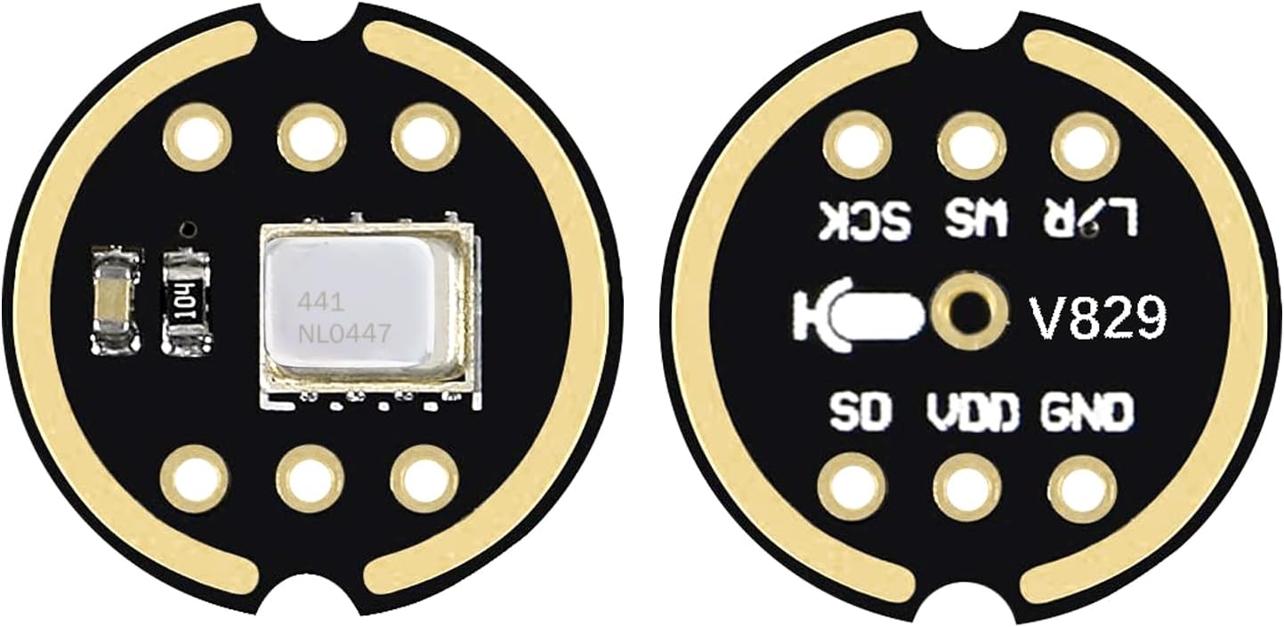
Figure 1: Front and back view of the INMP441 module, illustrating its compact form factor and pin layout.
2. Key Features
- High-Performance MEMS Sensor: Utilizes an advanced MEMS sensor for high sensitivity and low noise, ensuring clear and undistorted audio input.
- I2S Digital Interface: Transmits digital audio data via I2S, reducing signal interference and improving audio precision and dynamic range compared to analog microphones. Supports high-quality 24-bit audio sampling.
- Omnidirectional Sound Capture: Designed to capture sound from all directions (360°), making it suitable for applications like smart voice devices, voice assistants, and environmental monitoring.
- Excellent Audio Performance: Features a high signal-to-noise ratio of 61 dBA and a flat wideband frequency response from 60 Hz to 15 kHz for natural, high-resolution sound. Sensitivity: -26 dBFS.
- Low Power Consumption: Operates with a low current consumption of 1.4 mA, making it ideal for battery-powered devices and energy-efficient integrated projects.
- Compact Design: Small form factor facilitates easy integration into various embedded systems and IoT devices.
3. Package Contents
Each package contains:
- 6 x INMP441 Omnidirectional Microphone Modules
4. Setup and Connections
The INMP441 module features a standard I2S interface for digital audio communication. Proper connection to your development board is crucial for correct operation.
4.1 Pin Descriptions
| Pin | Description |
|---|---|
| SCK | Serial Data Clock for I2S interface. |
| WS | Word Select (Left/Right Channel Clock) for I2S interface. |
| L/R | Left/Right Channel Selection. If low, the microphone outputs the left channel signal. If high, it outputs the right channel signal. Note: Some modules may have this pin internally tied to GND, limiting stereo configuration. |
| SD | Serial Data Output of the I2S interface. |
| VCC | Input Voltage Supply (1.8V to 3.3V). |
| GND | Ground connection. |

Figure 2: Detailed view of the INMP441 module pins.
4.2 Connection Examples
Below are typical wiring diagrams for connecting the INMP441 module to a development board. Always ensure your board's I2S pins are compatible with the module's requirements.

Figure 3: Example connection diagram for INMP441 with a VIM3 GPIO board.
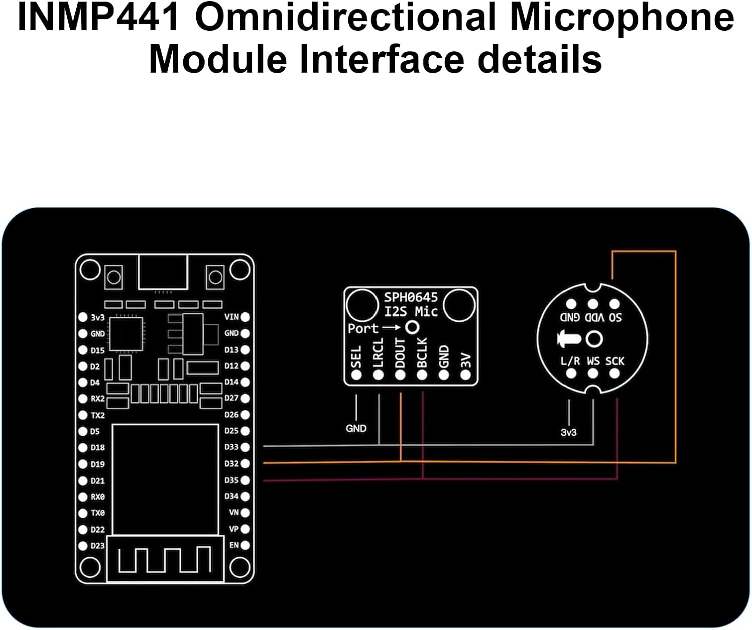
Figure 4: Example connection diagram for INMP441 with an ESP32 board.
5. Operating Instructions
Once the INMP441 module is correctly wired to your development board (e.g., ESP-32), you will need to configure the I2S peripheral in your microcontroller's firmware. This typically involves:
- Initializing the I2S Driver: Set up the I2S communication protocol, specifying the clock (SCK), word select (WS), and data (SD) pins.
- Configuring Audio Parameters: Define the sample rate (e.g., 44.1 kHz, 48 kHz), bit depth (24-bit), and channel mode (mono or stereo, depending on L/R pin configuration).
- Reading Audio Data: Use the I2S driver functions to read digital audio samples from the SD pin. These samples can then be processed, stored, or transmitted as needed for your application.
- Software Libraries: For platforms like ESP-32, various I2S audio libraries are available (e.g., within the Arduino IDE or ESP-IDF) that simplify the configuration and data acquisition process. Refer to your development board's documentation for specific library usage.
The omnidirectional nature of the microphone means it will pick up sound equally from all directions. Position the module appropriately for your desired sound source and environment.
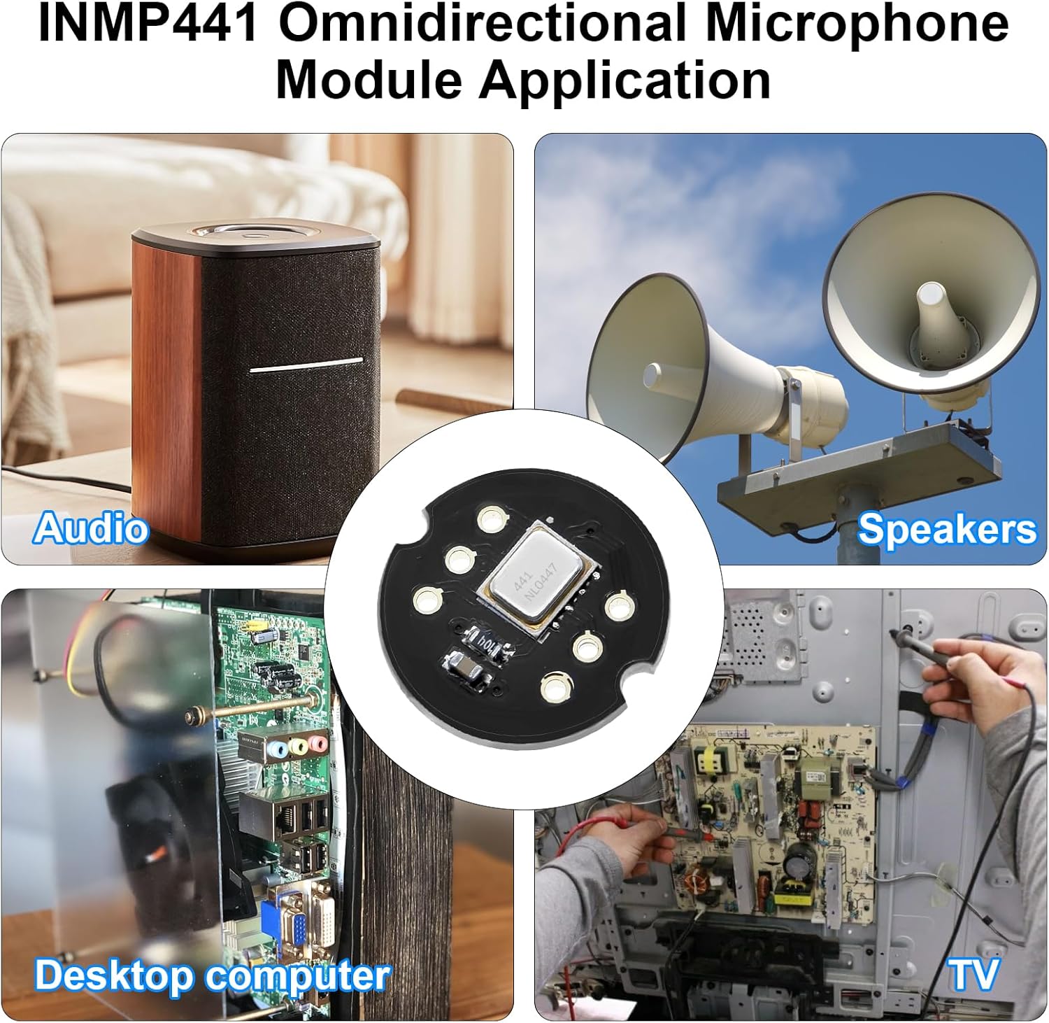
Figure 5: Example applications of the INMP441 module in audio systems and smart devices.
6. Maintenance
The INMP441 microphone module is a robust electronic component, but proper handling and care will ensure its longevity and performance:
- Keep Dry: Avoid exposure to moisture or liquids, as this can damage the internal electronics.
- Handle with Care: Avoid dropping or subjecting the module to strong impacts.
- Static Discharge: When handling, take precautions against electrostatic discharge (ESD) to prevent damage to sensitive components.
- Cleanliness: Keep the microphone opening free from dust and debris, which can affect audio quality. Use a soft, dry brush if cleaning is necessary.
7. Troubleshooting
- No Audio Output:
- Verify all wiring connections (VCC, GND, SCK, WS, SD) are secure and correct according to the pinout.
- Ensure the power supply (VCC) is within the specified range of 1.8V to 3.3V.
- Check your microcontroller's I2S configuration in the firmware. Confirm pin assignments, sample rate, and bit depth.
- Test with a known working I2S example code if available for your development board.
- Poor Audio Quality / Noise:
- Ensure proper grounding between the module and the development board.
- Check for electrical interference from nearby components or power lines. Try shielding or relocating the module.
- Verify that the I2S clock signals are stable and free from jitter.
- Adjust software gain settings if applicable, to avoid clipping or excessively low signal levels.
- L/R Channel Issues (for Stereo Applications):
- If attempting stereo operation, ensure the L/R pin is correctly configured (pulled high or low) and not inadvertently tied to GND on the module itself, which would force it into a single channel mode.
8. Specifications
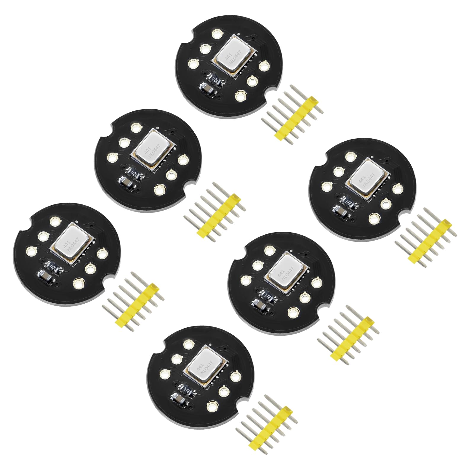
Figure 6: INMP441 Module dimensions.
| Parameter | Value |
|---|---|
| Digital Interface | I2S, 24-bit data |
| Signal-to-Noise Ratio (SNR) | 61 dBA |
| Sensitivity | -26 dBFS |
| Frequency Response | 60 Hz to 15 kHz |
| Current Consumption | 1.4 mA (low power) |
| Power Supply Rejection (PSR) | -75 dBFS |
| Input Voltage (VCC) | 1.8V to 3.3V |
| Polarity Pattern | Omnidirectional |
| Module Dimensions | Approx. 14.0mm x 14.0mm (0.55 inches) |
| Manufacturer | AYWHP |
| Weight (Package) | Approx. 10 g |
9. Warranty and Support
For any questions, technical assistance, or warranty claims regarding your INMP441 Omnidirectional Microphone Module, please contact the seller or manufacturer directly through the platform where the product was purchased. Please provide your order details and a clear description of the issue to facilitate prompt support.

