1. Introduction and Overview
The M9108 series actuators are designed for use with on-off, floating, proportional, or resistive controllers. These bidirectional actuators are engineered for easy installation on dampers with round shafts up to 3/4 inch (20 mm) in diameter or square shafts up to 5/8 inch (16 mm). They can be direct or remote mounted to a damper, or integrated with a valve using M9000-5xx Valve Linkage Kits.
A single M9108 model provides up to 70 lb·in (8 N·m) of torque. The angle of rotation is mechanically adjustable from 0 to 90 degrees in 5-degree increments. Integral auxiliary switches are available for end-stop indication or to perform switching functions at any angle within the selected rotation range. Position feedback is available via switches, a potentiometer, or a 0 (2) to 10 VDC signal.
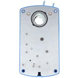
Figure 1: M9108 Electric Non Spring Return Actuator. This image shows the compact design of the actuator, highlighting its robust casing and connection points.
Key Features
- Control Inputs: Four control inputs accommodate various application needs.
- Output Position Feedback: Provides simple closed-loop control with accurate position sensing.
- Electronic Stall Detection: Enhances reliability by deactivating the motor upon detecting a stall condition.
- Master/Slave Operation: Allows synchronized control for two actuators in tandem applications.
- Zero and Span Adjustment (HGx models): Enables sequential operation of dampers from a single input signal (0 (2) to 10 VDC, 0 (4) to 20 VDC, or 0 (4) to 20 mA).
- Jumper-Selectable Rotation Direction: Simplifies installation, setup, and field adjustments.
- Manual Gear Release: Facilitates easy adjustments during installation.
- NPT Threaded Housing: Provides easy connection for electrical fittings.
- Actuator Type: 0 (2) to 10 VDC Proportional.
- Torque: 70 lb-in.
- Voltage: 24 VAC.
- Switch: SPDT.
- Fail Safe Mode: Non-Spring Return.
2. Safety Information
Read all instructions carefully before installing or operating the M9108 actuator. Failure to follow these instructions could result in product damage, property damage, or personal injury.
- Ensure all power is disconnected before performing any installation, wiring, or maintenance procedures.
- Installation and wiring must be performed by qualified personnel in accordance with all local and national electrical codes.
- Do not operate the actuator beyond its specified voltage and torque limits.
- Protect the actuator from moisture and extreme temperatures unless specifically rated for such conditions.
- Verify proper grounding to prevent electrical shock.
3. Installation (Setup)
Proper installation is crucial for the reliable operation of the M9108 actuator. Follow these general guidelines:
Mounting
- Ensure the mounting surface is stable and capable of supporting the actuator's weight and torque.
- The actuator can be direct or remote mounted to a damper. For direct mounting, ensure the damper shaft fits within the specified dimensions (round up to 3/4 in (20 mm) or square up to 5/8 in (16 mm)).
- For valve applications, use an appropriate M9000-5xx Valve Linkage Kit.
- Securely fasten the actuator to prevent movement during operation.
Wiring
- Disconnect all power before wiring.
- Connect the power supply (24 VAC) to the designated terminals.
- Wire the control inputs (0 (2) to 10 VDC Proportional) according to your controller's specifications.
- If using auxiliary switches (SPDT), connect them as required for end-stop indication or other switching functions.
- Utilize the NPT threaded housing for secure electrical conduit connections.
- Verify all connections are tight and correctly polarized.
4. Operation
Once installed and wired, the M9108 actuator operates based on the control signal received from your system.
Initial Power-Up
- Apply power to the actuator. The actuator may perform an initial calibration cycle.
- Observe the actuator's movement to ensure it responds correctly to the control signal.
Adjusting Rotation
- The angle of rotation can be mechanically adjusted from 0 to 90 degrees in 5-degree increments. Refer to the actuator's markings for precise adjustment.
- Use the jumper-selectable rotation direction feature to match the actuator's movement with the desired damper or valve action.
- For tandem applications, ensure master/slave operation is correctly configured for synchronized control.
5. Maintenance
The M9108 actuator is designed for minimal maintenance. However, periodic checks can ensure long-term reliability.
- Visual Inspection: Periodically inspect the actuator for any signs of physical damage, loose connections, or excessive dust accumulation.
- Cleaning: Keep the exterior of the actuator clean and free from debris. Do not use harsh chemicals or abrasive materials.
- Connection Checks: Ensure all electrical connections remain secure.
- Functionality Test: Occasionally cycle the actuator through its full range of motion to confirm proper operation and response to control signals.
No internal user-serviceable parts are present. For internal issues, contact qualified service personnel.
6. Troubleshooting
If the M9108 actuator is not functioning as expected, review the following common issues and solutions:
- Actuator Not Moving:
- Check power supply connections and voltage (24 VAC).
- Verify the control signal is present and within the specified range (0 (2) to 10 VDC).
- Ensure the manual gear release is not engaged.
- Check for any mechanical obstructions preventing movement.
- Incorrect Rotation Direction:
- Adjust the jumper-selectable rotation direction setting.
- Inaccurate Position Feedback:
- Verify wiring for position feedback (switches, potentiometer, or VDC signal).
- Ensure auxiliary switches are correctly set for the desired angles.
- Actuator Stalling:
- Check for excessive load or mechanical binding in the damper/valve linkage.
- The electronic stall detection feature will deactivate the motor to prevent damage; address the cause of the stall.
If problems persist after attempting these solutions, contact technical support.
7. Specifications
| Attribute | Value |
|---|---|
| Manufacturer | Generic |
| Part Number | M9108-GGC-2 |
| Item Model Number | M9108-GGC-2 |
| Product Dimensions (L x W x H) | 1 x 1 x 1 inches |
| Actuator Type | 0 (2) to 10 VDC Proportional |
| Torque | 70 lb-in |
| Voltage | 24 VAC |
| Switch | SPDT |
| Fail Safe Mode | Non-Spring Return |
| Damper Shaft Compatibility (Round) | Up to 3/4 in (20 mm) |
| Damper Shaft Compatibility (Square) | Up to 5/8 in (16 mm) |
| Angle of Rotation | 0 to 90 degrees (adjustable in 5-degree increments) |
| Date First Available | February 10, 2025 |
8. Warranty and Support
For specific warranty information and technical support, please refer to the documentation provided with your purchase or contact the manufacturer directly. Keep your purchase receipt as proof of purchase for any warranty claims.


