1. Introduction
The Greystone AVDTXX Duct Mount Air Velocity Transmitter is a precision instrument designed for accurate air velocity and temperature measurements within HVAC/R systems and Building Automation applications. This device offers field-selectable ranges and supports both Metric and Imperial units, making it adaptable to diverse operational requirements. Its robust, duct-mount probe with an adjustable collar ensures straightforward installation in both round and rectangular ducts, providing real-time data for optimal system performance.
This manual provides essential information for the safe and effective installation, operation, and maintenance of your AVDTXX transmitter. Please read it thoroughly before proceeding with any procedures.
2. Safety Information
Always observe the following safety precautions to prevent injury and damage to the device:
- Installation and servicing must be performed by qualified personnel only, in accordance with all local and national electrical codes.
- Disconnect power to the device before performing any wiring connections or maintenance.
- Ensure proper grounding to prevent electrical shock.
- Do not operate the device outside its specified voltage and current ratings.
- Avoid exposing the device to excessive moisture, dust, or extreme temperatures beyond its operating range.
- Handle the probe with care to avoid bending or damaging the sensing elements.
3. Product Overview
The AVDTXX transmitter is engineered for reliability and accuracy in demanding environments. Key features include:
- Measures air velocity and temperature simultaneously.
- Field-selectable velocity ranges: 0-2, 10, 20 m/s or 0-400, 2000, 4000 fpm.
- Analog outputs: 0-10 Vdc or 4-20 mA for both velocity and temperature.
- Optional potential-free SPDT relay with adjustable setpoint and hysteresis for automation integration.
- Durable stainless steel duct mount probe with adjustable flange (50–180mm insertion).
- Rapid thermal shift compensation for stable and accurate performance.
- Compact IP54 enclosure.
3.1. What's in the Box
Upon unpacking, verify that the following items are included:
- 1 unit of Air Velocity Transmitter (Greystone AVDTXX)
- Stainless steel probe
- Adjustable flange for duct mounting
- Instruction manual (this document)
3.2. Product Components

Figure 1: Greystone AVDTXX Air Velocity Transmitter, front-side view.
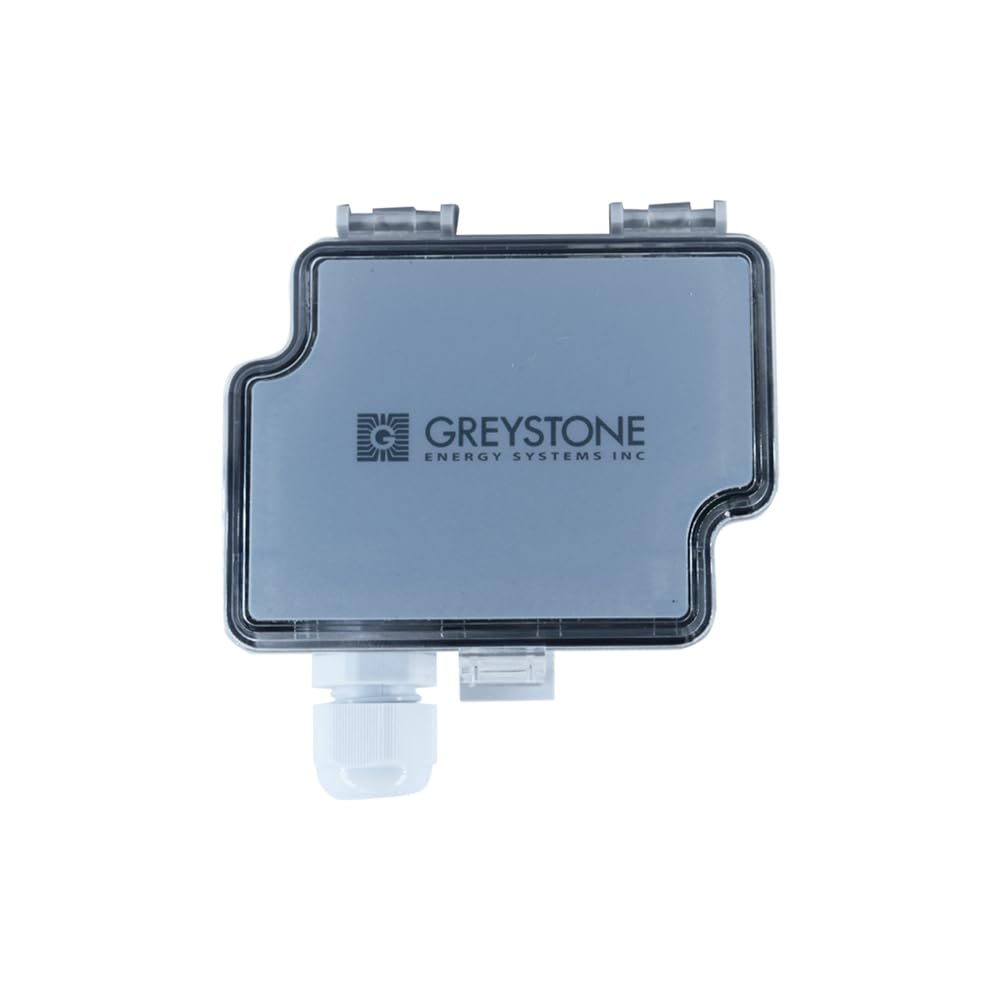
Figure 2: Top view of the AVDTXX transmitter, showing the enclosure and cable gland.

Figure 3: Side view of the AVDTXX with the stainless steel duct mount probe.

Figure 4: The AVDTXX probe and adjustable collar for duct insertion.

Figure 5: Internal view of the AVDTXX transmitter, showing the circuit board and terminal blocks for wiring.

Figure 6: Typical applications for the AVDTXX transmitter, including HVAC system optimization and air quality monitoring.
4. Setup and Installation
Proper installation is crucial for accurate measurements and long-term reliability. Follow these steps carefully:
4.1. Mounting Location
- Select a location in the duct where airflow is laminar and representative of the overall flow. Avoid areas immediately after bends, dampers, or fans.
- Ensure sufficient space for probe insertion and maintenance.
4.2. Duct Mounting
- Drill a hole in the duct appropriate for the probe diameter.
- Insert the stainless steel probe into the duct.
- Adjust the collar to achieve the desired insertion depth (50–180mm) and secure it firmly to the duct using appropriate fasteners (not supplied).
- Ensure the probe is oriented correctly within the airflow for optimal measurement.
4.3. Electrical Wiring
Before wiring, ensure all power is disconnected. Refer to the internal wiring diagram on the device for specific terminal assignments.
- Power Supply: Connect the appropriate power supply (e.g., 24 Vac/dc) to the designated power terminals.
- Analog Outputs: Connect the 0-10 Vdc or 4-20 mA output signals for temperature (TOUT) and velocity (VOUT) to your Building Management System (BMS) or data acquisition system.
- Relay Output (Optional): If equipped, connect the potential-free SPDT relay terminals (NC, COM, NO) to your control system. The relay supports up to 250 Vac or 30 Vdc, 6A.
4.4. Jumper Settings (Field-Selectable Ranges)
The AVDTXX features jumper-selectable ranges for velocity. Consult the internal labeling or the device's specific documentation for the correct jumper positions to select your desired velocity range (e.g., 0-2, 10, 20 m/s or 0-400, 2000, 4000 fpm). Ensure power is off before adjusting jumpers.
5. Operating Instructions
Once installed and powered, the AVDTXX will begin measuring air velocity and temperature. The device is designed for continuous operation.
5.1. Data Output
- Temperature Output (TOUT): Provides a linear 0-10 Vdc or 4-20 mA signal corresponding to the measured temperature (0–50°C / 32–122°F).
- Velocity Output (VOUT): Provides a linear 0-10 Vdc or 4-20 mA signal corresponding to the measured air velocity, based on the selected range.
5.2. Relay Function (Optional)
If the optional relay is installed, it can be configured to switch based on a user-defined setpoint and hysteresis for either velocity or temperature. This allows for direct control of external devices (e.g., fans, alarms) based on measured conditions.
5.3. Display (if applicable)
Some models may feature an alternating display showing both velocity and temperature readings. Refer to your specific model's features for display functionality.
6. Maintenance
The AVDTXX transmitter is designed for minimal maintenance. However, periodic checks can ensure continued accuracy and performance.
- Cleaning: Periodically inspect the probe for dust or debris accumulation. Gently clean the probe with a soft, dry cloth. Do not use abrasive cleaners or solvents.
- Calibration: The device is factory calibrated. If recalibration is required, it should be performed by qualified personnel in a controlled environment. The device features rapid calibration at 22°C with a 10-minute stabilization period.
- Connections: Ensure all electrical connections remain secure and free from corrosion.
7. Troubleshooting
If you encounter issues with your AVDTXX transmitter, refer to the following common problems and solutions:
| Problem | Possible Cause | Solution |
|---|---|---|
| No output signal | No power; Incorrect wiring; Faulty device. | Check power supply; Verify wiring connections; Contact technical support if power and wiring are correct. |
| Inaccurate readings | Probe dirty; Incorrect jumper settings; Probe not properly positioned in duct; Airflow not laminar. | Clean probe; Verify jumper settings for desired range; Reposition probe; Relocate sensor to a more stable airflow area. |
| Relay not switching | Incorrect setpoint/hysteresis; Wiring issue; Measured value not reaching setpoint. | Adjust setpoint/hysteresis; Check relay wiring; Verify measured velocity/temperature. |
| Intermittent readings | Loose connections; Electrical interference. | Check all wiring connections; Ensure proper shielding and grounding; Isolate from sources of electrical noise. |
If the problem persists after attempting these solutions, please contact INSTRUKART technical support.
8. Specifications
| Parameter | Value |
|---|---|
| Model Number | AVDTXX-1 |
| Measurement | Air Velocity, Temperature |
| Velocity Ranges (Jumper-Selectable) | 0-2, 10, 20 m/s; 0-400, 2000, 4000 fpm |
| Velocity Accuracy | ±0.2–1.0 m/s + 5% (Metric); ±20–200 fpm + 5% (Imperial) |
| Temperature Range | 0–50°C (32–122°F) |
| Temperature Accuracy | ±0.5°C |
| Output Signals | Signal 1 (TOUT): 0-10 Vdc or 4-20 mA (linear to temperature) Signal 2 (VOUT): 0-10 Vdc or 4-20 mA (linear to m/s) |
| Relay (Optional) | Potential-free SPDT (NC, COM, NO), adjustable setpoint/hysteresis, 250 Vac or 30 Vdc, 6A |
| Thermal Shift | ±0.8% FS/°C |
| Enclosure Rating | IP54 |
| Certifications | CE, RoHS |
| Probe Insertion Length | 50–180mm (adjustable) |
| Manufacturer | INSTRUKART |
9. Warranty and Support
For warranty information and technical support, please contact INSTRUKART directly. Details regarding warranty periods and terms are typically provided at the point of purchase or can be obtained from the manufacturer's official website.
When contacting support, please have your product model number (AVDTXX-1) and any relevant purchase information ready.


