
XYGStudy ESP32-S3-A7670E-4G
Contents
ESP32-S3 A7670E 4G Development Board User Manual
Model: ESP32-S3-A7670E-4G | Brand: XYGStudy
1. Introduction
This manual provides comprehensive instructions for the setup, operation, and maintenance of the ESP32-S3 A7670E 4G Development Board. This board integrates an ESP32-S3R2 chip with an A7670E cellular module, offering LTE Cat-1 / 2G, WiFi, Bluetooth, telephone call, SMS, and GNSS positioning capabilities. It is designed for various IoT applications, including portable WiFi solutions, outdoor monitoring, and smart home systems.
Please read this manual thoroughly before using the device to ensure proper functionality and safety.
2. Package Contents
Verify that all items listed below are included in your package. If any items are missing or damaged, please contact customer support.
- ESP32-S3-A7670E-4G Development Board x1
- Transparent acrylic case and screws pack x1
- GNSS ceramic antenna x1
- OV2640 camera x1
- 8Ω 2W 2030 speaker x1
- 40PIN yellow straight pin header x1
- USB Type-A to Type-C cable 1m x1
- FPC antenna x1
- Screwdriver x1
- 2P screw terminal x1
- Double-side tape (4PCS) x1

Image: All components included in the package, laid out for inspection.
3. Key Features
- ESP32-S3R2 Chip: High-performance Xtensa 32-bit LX7 dual-core processor, up to 240 MHz.
- Memory: 512KB SRAM, 384KB ROM, 2MB PSRAM, 16MB Flash memory.
- Wireless Connectivity: Integrated 2.4GHz Wi-Fi and Bluetooth LE dual-mode.
- Cellular Module: A7670E-FASE, supporting 4G Cat-1/2G networking, GNSS positioning, telephone calls, and SMS.
- USB Interface: Onboard USB switching IC and DIP switch for A7670E module debugging or dial-up internet.
- Power Management: Lithium battery charging, solar charging, power management, and real-time battery capacity measurement.
- Battery Support: Onboard 18650 battery holder (battery not included) and VBAT pin header for external 3.7V lithium battery with anti-reverse protection.
- Peripheral Interfaces: Camera interface, TF card slot, USB port, 38PIN header for expansion.
- DIP Switches: For camera on/off, USB channel switching, and power control for reduced consumption.
- Included Accessories: GNSS high-precision ceramic antenna, OV2640 camera, mini speaker, acrylic case.

Image: Overview diagram highlighting the main features and capabilities of the development board.
4. Board Layout and Pinout
Understanding the board layout and pin definitions is crucial for proper connection and development.

Image: Top-down view of the development board with numbered callouts for various components and interfaces.

Image: Detailed pinout diagram showing GPIOs, power pins, and other interface connections.
For a complete list of component functions and pin definitions, refer to the online development resources provided by XYGStudy.
5. Setup Guide
5.1. Assembling the Acrylic Case
The transparent acrylic case provides protection for the development board. Follow these steps for assembly:
- Carefully remove the protective film from both sides of all acrylic pieces.
- Align the bottom acrylic plate with the mounting holes on the ESP32-S3-A7670E-4G board.
- Secure the board to the bottom plate using the provided screws and standoffs.
- Attach the top acrylic plate, ensuring all cutouts align with the board's components and connectors.
- Fasten the top plate with the remaining screws.

Image: The development board enclosed within its transparent acrylic case, showcasing the assembled product.
5.2. Connecting Peripherals
- GNSS Antenna: Connect the GNSS ceramic antenna to the IPEX connector labeled "GNSS" on the board. Position the antenna with a clear view of the sky for optimal signal reception.
- OV2640 Camera: Connect the OV2640 camera module to the 24PIN camera interface. Ensure correct orientation before inserting.
- Speaker: Connect the 8Ω 2W 2030 speaker to the designated speaker terminals.
- FPC Antenna: Connect the FPC antenna to the appropriate connector for cellular communication.
- SIM Card: Insert a Nano SIM card into the SIM card slot with the gold contacts facing down and the notched corner aligned.
- TF Card: Insert a TF (MicroSD) card into the TF card slot if storage is required for your application.
5.3. Powering the Board
The board supports multiple power input methods:
- USB Type-C: Connect the provided USB Type-A to Type-C cable to the board's USB-C port and to a 5V power source (e.g., computer USB port, USB wall adapter).
- 18650 Lithium Battery: Insert an 18650 lithium battery (not included) into the onboard battery holder. Ensure correct polarity.
- External 3.7V Lithium Battery: Connect an external 3.7V lithium battery to the VBAT pin header. The board includes anti-reverse protection.
- Solar Panel: Connect a compatible solar panel (5.5V-6V/5W or 18V/10W recommended) to the solar panel input interface for charging.
Caution: Ensure correct voltage and polarity when connecting external power sources to prevent damage to the board.
6. Operation
6.1. Initial Power On and Boot
After connecting a power source, the board will power on. The onboard LEDs will indicate power status and network activity. Press the RESET button if the board does not start or needs to be restarted.
6.2. Development Environment Setup
To develop applications for the ESP32-S3 A7670E board, you will need to set up a development environment. XYGStudy provides online resources and tutorials for this purpose, typically involving the ESP-IDF (Espressif IoT Development Framework) or Arduino IDE.
- Refer to the official Espressif documentation for ESP32-S3 development.
- Download and install the necessary drivers for the USB-to-UART bridge.
- Utilize the provided demo codes and examples for 4G portable WiFi, IoT applications, and other functionalities.
6.3. Cellular (4G/2G) and GNSS Functionality
The A7670E module enables cellular communication and GNSS positioning.
- Network Connection: Ensure a valid SIM card is inserted and the FPC antenna is connected. The module supports LTE Cat-1 and 2G networks.
- GNSS Positioning: With the GNSS ceramic antenna connected and a clear view of the sky, the module can acquire GPS, BeiDou, and GLONASS signals for accurate positioning.
- Telephone Call & SMS: The A7670E module supports telephone calls and SMS functionality via AT commands. An onboard microphone and speaker are available for audio.
- Dial-up Internet: The onboard USB switching IC and DIP switch allow you to switch the USB interface to the A7670E module for PC dial-up internet or direct debugging.

Image: Illustration of the board's multi-band support for LTE Cat-1 and 2G networks, indicating global applicability.
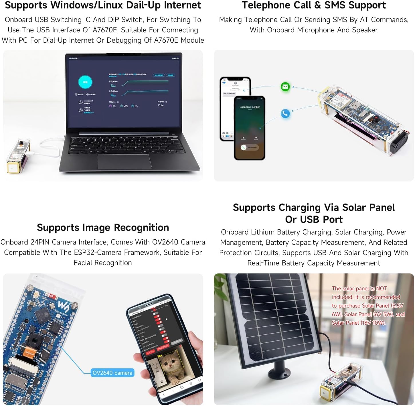
Image: Illustration of the board's GNSS positioning capabilities, supporting GPS, BeiDou, and GLONASS.
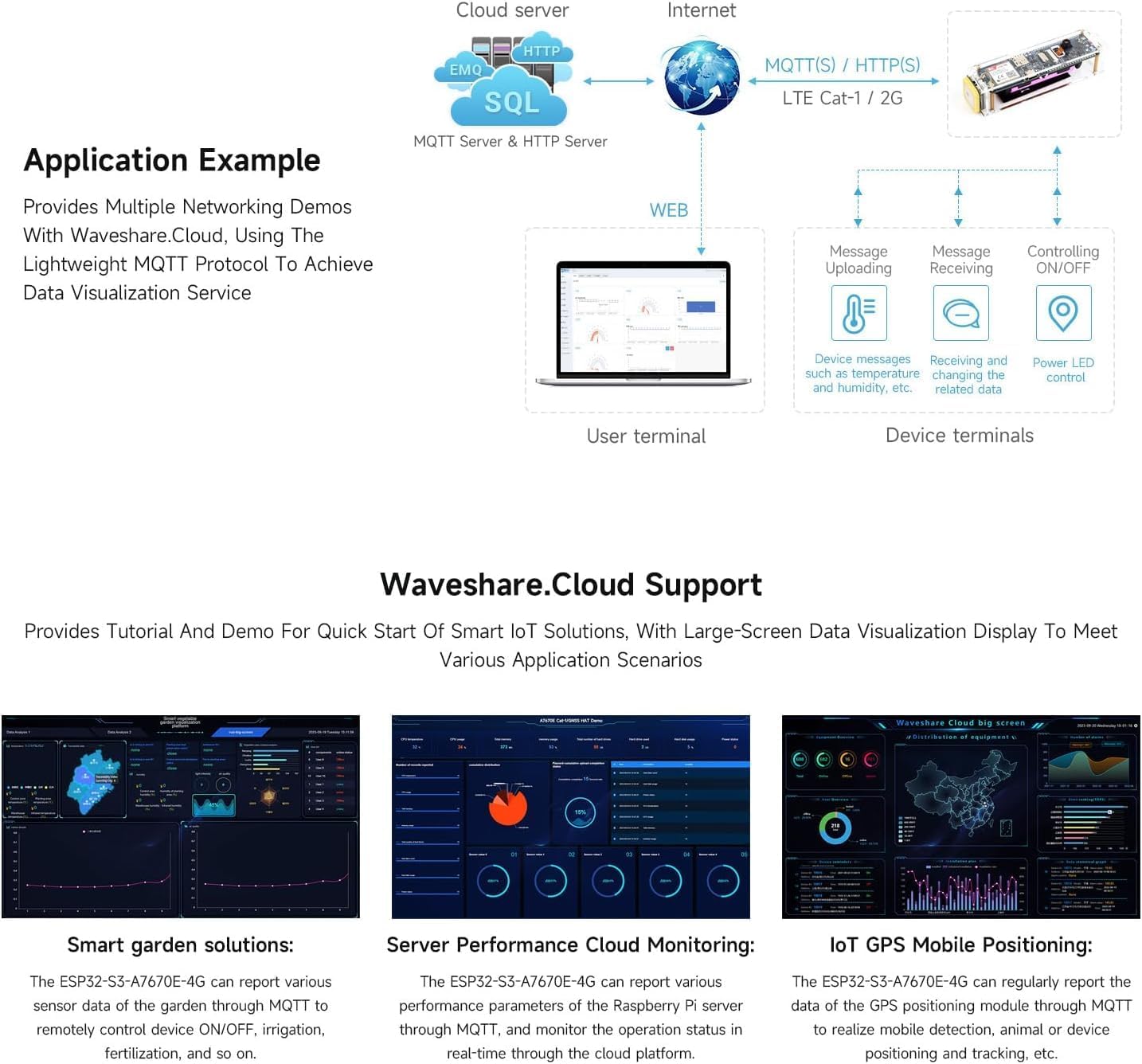
Image: The development board connected to a laptop, demonstrating its capability for dial-up internet access via the A7670E module.

Image: The development board demonstrating telephone call and SMS functionality, with an integrated speaker and microphone.
6.4. Portable 4G WiFi Solution
The ESP32-S3 A7670E board can be configured as a portable 4G WiFi hotspot. This allows other devices to connect to the internet via the board's cellular connection.
- Connect the ESP32-S3 to the A7670E via USB.
- Activate the WiFi AP hotspot functionality through firmware.
- Smartphones, laptops, and other WiFi-enabled devices can then connect to the board's WiFi network.
Image: Visual representation of the development board acting as a portable 4G WiFi hotspot, connecting various devices to the internet.
6.5. Image Recognition
With the OV2640 camera connected, the board supports image recognition applications using the ESP32-Camera framework.
Image: The development board demonstrating image recognition capabilities using the OV2640 camera, suitable for facial recognition and other visual tasks.
7. Maintenance
- Cleaning: Use a soft, dry cloth to clean the board and acrylic case. Avoid using liquids or abrasive cleaners.
- Storage: Store the board in a cool, dry place away from direct sunlight and extreme temperatures.
- Firmware Updates: Regularly check for firmware updates from XYGStudy or Espressif to ensure optimal performance and access to new features.
- Battery Care: If using an 18650 battery, follow standard lithium battery safety guidelines. Do not overcharge or deep discharge.
8. Troubleshooting
| Problem | Possible Cause | Solution |
|---|---|---|
| Board does not power on. | No power supply; incorrect power connection; faulty cable. | Check USB cable connection and power source. Ensure 18650 battery is charged and correctly inserted. Verify external power supply voltage and polarity. |
| Cannot connect to cellular network. | No SIM card; invalid SIM; FPC antenna not connected; poor signal; incorrect APN settings. | Ensure SIM card is correctly inserted and active. Connect FPC antenna. Move to an area with better signal. Configure APN settings in your firmware. |
| GNSS positioning is inaccurate or fails. | GNSS antenna not connected; obstructed view of sky; indoor use. | Connect GNSS ceramic antenna. Ensure antenna has a clear, unobstructed view of the sky. Test outdoors. |
| USB communication issues with PC. | Missing drivers; incorrect USB switch setting; faulty USB cable. | Install necessary USB-to-UART drivers. Check the position of the onboard USB switching DIP switch. Try a different USB cable. |
| Camera not working. | Camera not connected correctly; camera DIP switch off; firmware issue. | Ensure OV2640 camera is securely connected. Check the camera on/off DIP switch. Verify camera initialization in your firmware. |
For further assistance, refer to the online development resources or contact XYGStudy customer support.
9. Technical Specifications
| Feature | Detail |
|---|---|
| Model Number | ESP32-S3-A7670E-4G |
| Main Chip | ESP32-S3R2 (Xtensa 32-bit LX7 dual-core processor) |
| Clock Speed | Up to 240 MHz |
| Memory | 512KB SRAM, 384KB ROM, 2MB PSRAM, 16MB Flash |
| Wi-Fi | 2.4GHz, 802.11 b/g/n |
| Bluetooth | Bluetooth LE 5.0 |
| Cellular Module | A7670E-FASE |
| Cellular Bands | LTE Cat-1 / 2G (Specific bands depend on A7670E variant, typically FDD-LTE B1/B3/B5/B7/B8/B20) |
| GNSS Support | GPS, BeiDou, GLONASS |
| Power Input | USB Type-C (5V), 18650 battery, external 3.7V lithium battery, solar panel (5.5V-18V) |
| Dimensions | Approx. 125mm x 34mm x 31.6mm (with case) |
| Operating Temperature | -30°C to +80°C (Module dependent) |
Image: A visual representation of the board's communication parameters and operating specifications.
10. Warranty and Support
10.1. Warranty Information
This product is covered by a standard manufacturer's warranty against defects in materials and workmanship. Please retain your proof of purchase for warranty claims. The warranty period typically begins from the date of purchase. For specific warranty terms and conditions, please refer to the documentation provided with your purchase or contact XYGStudy directly.
The warranty does not cover damage caused by:
- Improper installation or use not in accordance with this manual.
- Accidents, abuse, neglect, or unauthorized modifications.
- Exposure to extreme temperatures, humidity, or corrosive environments.
- Power surges or incorrect voltage supply.
10.2. Technical Support
For technical assistance, development resources, or inquiries regarding your ESP32-S3 A7670E 4G Development Board, please contact XYGStudy customer support. Online resources, including tutorials and demo examples, are available to assist with your projects.
Contact Information:
- Refer to the contact details provided on the product packaging or the official XYGStudy website.
- For resources, you may contact XYGStudy via Amazon message as mentioned in the product description.
Documents and downloads
Ask a question about this manual
Ask about setup, troubleshooting, compatibility, parts, safety, or missing instructions. Manuals+ will review the question and use this page’s manual context to help answer it.