1. Product Overview
The BUUBO DSO2512G is a dual-channel digital oscilloscope designed for various applications including single-chip debugging, car maintenance, home appliance maintenance, DIY projects, electronic competitions, power supply debugging, and frequency converter analysis. It integrates a 120M bandwidth oscilloscope with a signal generator, offering comprehensive measurement and analysis capabilities.
Key features include high-speed signal acquisition, a 2.8-inch display, and a built-in signal generator capable of outputting various waveforms.

Figure 1: BUUBO DSO2512G Digital Oscilloscope and included accessories, including probes, USB cable, and carrying case.
2. Specifications
| Feature | Specification |
|---|---|
| Channels | 2 |
| Bandwidth | 120M (single channel), 60M (dual channel) |
| Sampling Rate | 500M |
| Display | 2.8-inch |
| Trigger Modes | Auto, Normal, Single |
| Signal Generator Output Amplitude | 2.5V |
| Signal Generator Sine Wave Frequency | 0~10MHz |
| Signal Generator Other Waveform Frequency | 0~2MHz |
| Accuracy | Up to 0.1Hz (signal generator) |
| Measurement Options | Frequency, Peak-to-Peak, Duty cycle, Amplitude, RMS, Average, Period, +Pulse width, -Pulse width, Max, Min, Top, Base, -Duty cycle |
| Battery | 1 * lithium battery, 4000mAh |
| Impedance | 1M |
| Storage Depth | 128Kbit |
| Time Base | 5ns~10s |
| Vertical Sensitivity | 10mV/div~10V/div |
| XY Mode | Supported |
| FFT | Supported |
3. Setup and Initial Use
3.1 Unpacking
Carefully remove the oscilloscope and all accessories from the packaging. Verify that all components listed in the packing list are present. The standard package includes the DSO2512G unit, oscilloscope probes, a USB cable, and a carrying case.

Figure 2: Side view of the DSO2512G, highlighting the dual channel input ports.
3.2 Charging the Battery
The device is equipped with a built-in 4000mAh lithium battery. Before first use, it is recommended to fully charge the oscilloscope using the provided USB cable and a compatible USB power adapter (not included). The charging indicator will typically show the charging status.
3.3 Connecting Probes
Connect the oscilloscope probes to the BNC input connectors on the top of the device. Ensure a secure connection. For accurate measurements, it is crucial to properly calibrate the probes before use, especially when switching between 1X and 10X attenuation settings.
4. Operating Instructions
4.1 Power On/Off
Press and hold the power button (location typically on the side or front panel) to turn the device on or off. The display will illuminate upon successful power-on.
4.2 Basic Waveform Display
After powering on, connect a signal source to one of the input channels. The oscilloscope will automatically attempt to display the waveform. Use the navigation buttons (OK, Auto, Menu, Single, Save, Run/Stop, F1, m/V, s, ns, Y) to adjust settings.

Figure 3: Front view of the DSO2512G, illustrating the display and control button layout for operation.
4.3 Trigger Modes
The DSO2512G supports three trigger modes:
- Auto Trigger: Continuously updates the waveform without requiring a specific trigger event. Suitable for observing stable, repetitive signals.
- Normal Trigger: Requires a waveform trigger event to update the display. The display holds the last waveform if no trigger occurs. Useful for capturing specific events.
- Single Trigger: Captures a single frame of the waveform and then stops automatically after the trigger condition is met. Ideal for capturing transient or non-repetitive events.
4.4 Signal Generator Function
The oscilloscope includes a built-in signal generator. The output port for the signal generator is typically located at the bottom of the device. It can generate various waveforms with a 2.5V amplitude.
- Sine Waves: Frequency adjustable from 0 to 10MHz.
- Other Waveforms (Square, Triangle, Half-wave, Singh waves): Frequency adjustable from 0 to 2MHz.
The accuracy of the signal generator is up to 0.1Hz. This function is useful for probe calibration, driving MOS tubes, and testing distortion.
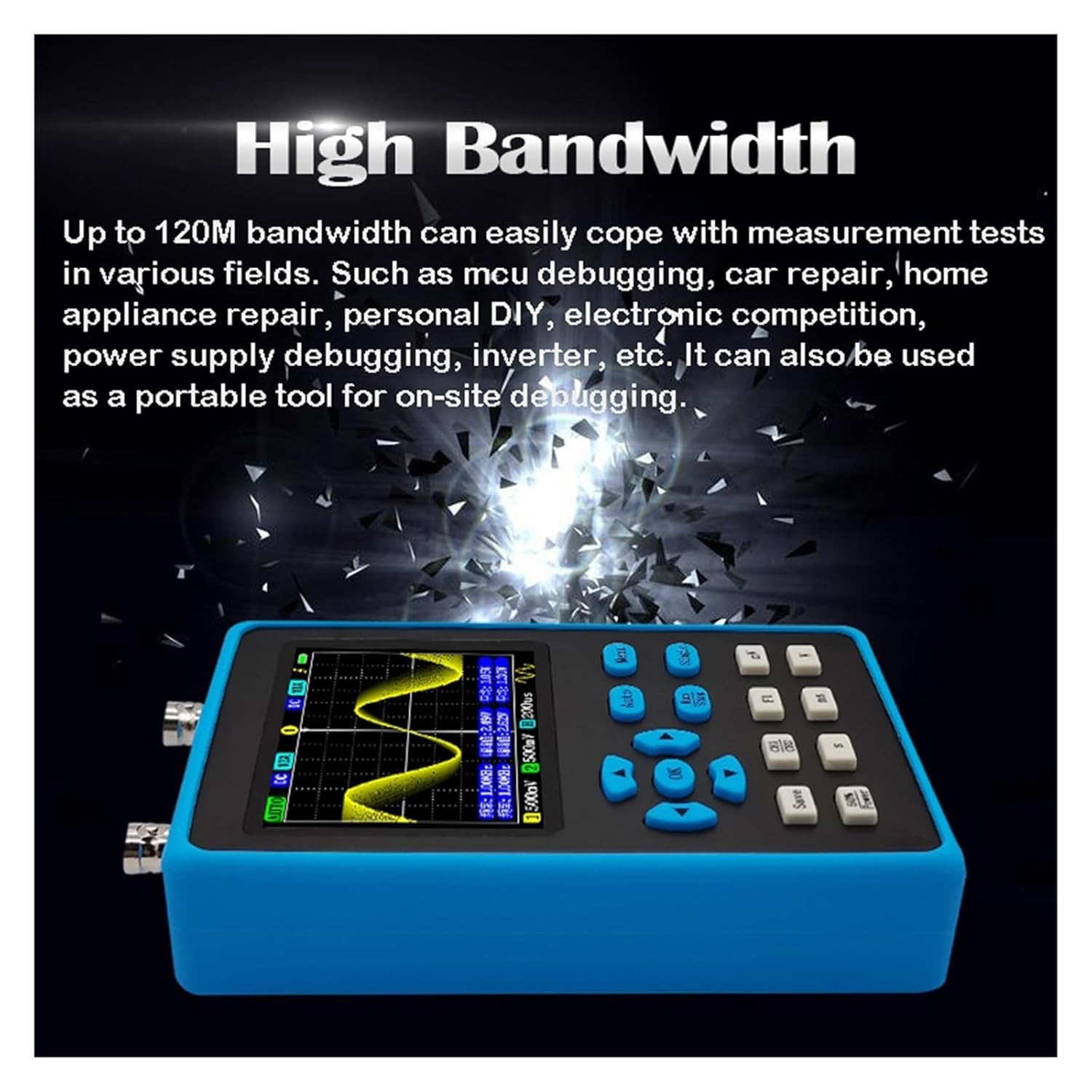
Figure 4: Bottom view of the DSO2512G, indicating the signal generator output ports (red for signal, black for GND).
4.5 Waveform Saving and Export
The device allows for one-click saving of screen waveforms. Up to 250 waveforms can be stored internally. To view saved waveforms, enter the waveform preview page and select a thumbnail to observe the full screen. Unwanted waveforms can be deleted.
Waveform maps can be exported to a computer via USB cable connection (up to 50 at a time) for further analysis or sharing.
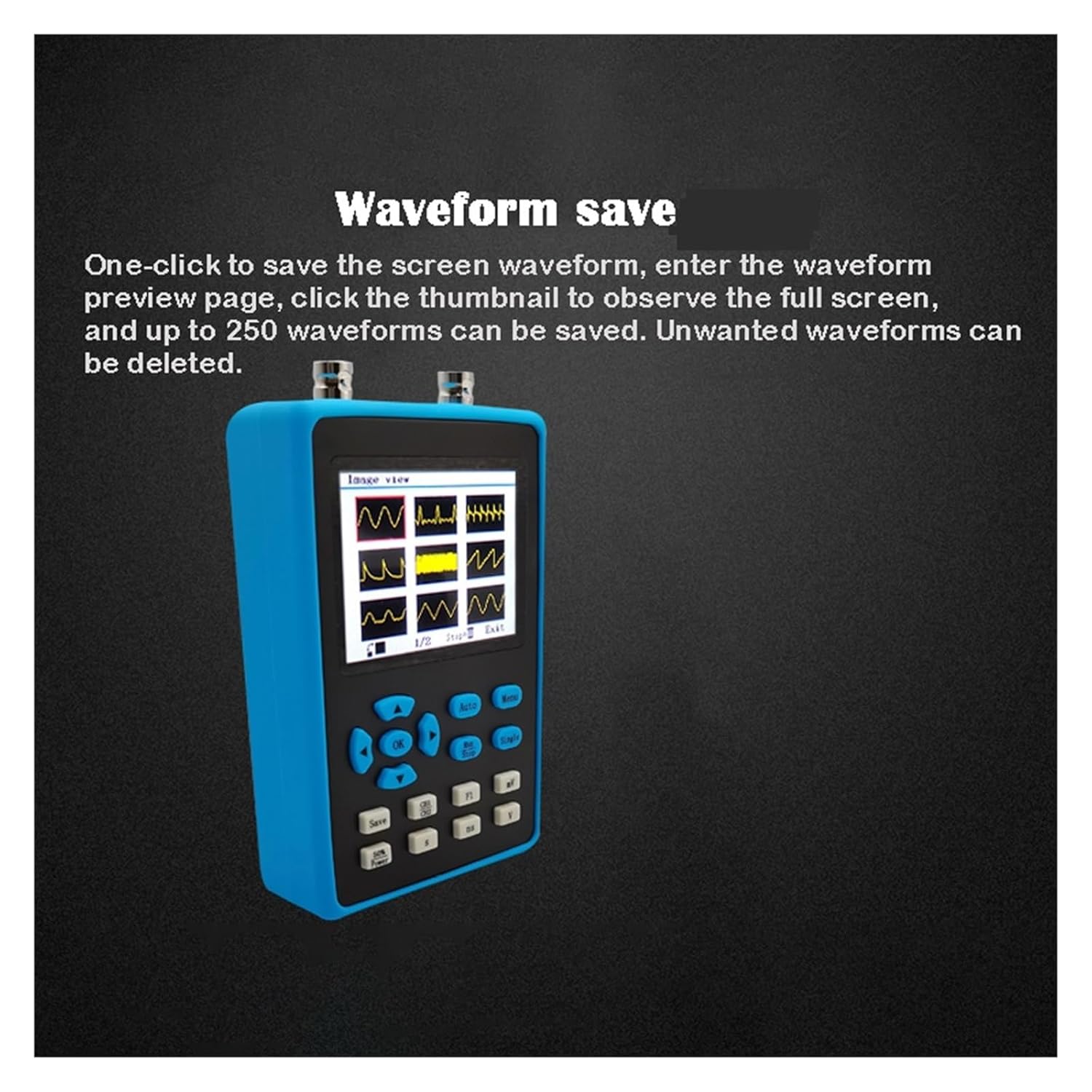
Figure 5: The waveform save and preview interface on the DSO2512G display.
4.6 Waveform Scaling and Analysis
After stopping a waveform capture, you can drag the waveform from left to right on the screen to expand specific areas of interest. This allows for detailed observation and analysis of waveform characteristics, aiding in problem diagnosis.
5. Maintenance and Care
- Cleaning: Use a soft, dry cloth to clean the device. Do not use abrasive cleaners or solvents.
- Storage: Store the oscilloscope in a cool, dry place away from direct sunlight and extreme temperatures. Use the provided carrying case for protection during transport and storage.
- Battery Care: To prolong battery life, avoid fully discharging the battery frequently. If storing for extended periods, charge the battery to approximately 50% every few months.
- Probe Care: Handle probes carefully. Avoid bending or kinking the cables. Store them properly to prevent damage to the tips.
6. Troubleshooting
6.1 No Display After Power On
- Check if the battery is charged. Connect the USB cable and attempt to power on while charging.
- Ensure the power button is pressed and held sufficiently.
6.2 Unstable Waveform Display
- Adjust the trigger level and trigger mode (Auto, Normal, Single) to suit the input signal.
- Verify probe connections are secure and properly calibrated.
- Check the input signal source for stability.
6.3 Incorrect Measurements
- Ensure probes are correctly calibrated for the attenuation setting (1X/10X).
- Verify the vertical sensitivity (V/div) and time base (s/div) settings are appropriate for the signal.
- Check for proper grounding of the circuit under test.
6.4 Signal Generator Not Outputting
- Ensure the signal generator function is enabled and configured correctly in the menu.
- Verify connections to the signal generator output ports.
7. Warranty and Support
For warranty information and technical support, please refer to the documentation provided with your purchase or contact BUUBO customer service. Keep your purchase receipt as proof of purchase.
Note: The manufacturer's warranty typically covers defects in materials and workmanship under normal use. Damage caused by misuse, unauthorized modification, or improper handling is not covered.