
1. Introduction
This manual provides comprehensive instructions for the assembly, setup, operation, and maintenance of the Giwnhvx Dual Spherical Rotating LED Kit, Model 500435433A1. This kit is designed for enthusiasts interested in DIY electronics and microcontroller projects, culminating in a unique spherical LED display with remote control capabilities.
Note: This is a DIY kit requiring soldering. Basic soldering skills and familiarity with electronic components are recommended for successful assembly.
2. Package Contents
Verify that all components listed below are present in your package before beginning assembly.
- 1 x Spherical Rotating DIY Welding Kit (includes main control board, side panels, LEDs, and various electronic components)
- 1 x Downloader
- 1 x Remote Control
- Acrylic base and support structures

Figure 2.1: All components included in the Giwnhvx Dual Spherical Rotating LED Kit, including circuit boards, LEDs, resistors, capacitors, acrylic parts, and the downloader module.
3. Specifications
| Feature | Detail |
|---|---|
| Product Name | Spherical Rotating DIY Welding Kit |
| Product Model | TJ-56-347 (Internal Kit Model) / 500435433A1 (Manufacturer Model) |
| Working Voltage | DC 5V |
| Rotating Diameter | 166mm |
| Number of LEDs | 56 Red LEDs, 56 Blue LEDs (Total 112) |
| Display Characters | Up to 60 Chinese characters or 100 English characters |
| Main Control Board Size | 125 x 48mm |
| Side Panel Size | 90 x 75mm |
| Material | PCB, Electronic Components, Acrylic |
4. Setup and Assembly
This section outlines the general steps for assembling your Giwnhvx Dual Spherical Rotating LED Kit. Detailed instructions for each component are typically provided with the physical kit. Ensure you have appropriate soldering tools and safety equipment.
- Component Identification: Before soldering, identify all components using the provided component list and circuit diagrams.
- Soldering Components:
- Begin by soldering smaller components (resistors, diodes) onto the main control board and side panels.
- Proceed with larger components (capacitors, ICs, LED arrays). Pay close attention to polarity for LEDs and electrolytic capacitors.
- Solder the 56 red and 56 blue LEDs onto the curved side panels as indicated in the kit's specific instructions.
- Motor and Base Assembly:
- Assemble the acrylic base and secure the motor in its designated position.
- Mount the main control board onto the motor shaft or supporting structure.
- Connecting Components:
- Connect the soldered LED side panels to the main control board.
- Connect the power supply module and remote control receiver board to the main control board.
- Initial Power-Up and Testing:
- Before full assembly, perform a preliminary power-up to check for basic functionality and correct soldering.
- Ensure the motor rotates smoothly and LEDs illuminate.
- Final Enclosure Assembly: Secure all acrylic panels and covers to complete the physical structure.
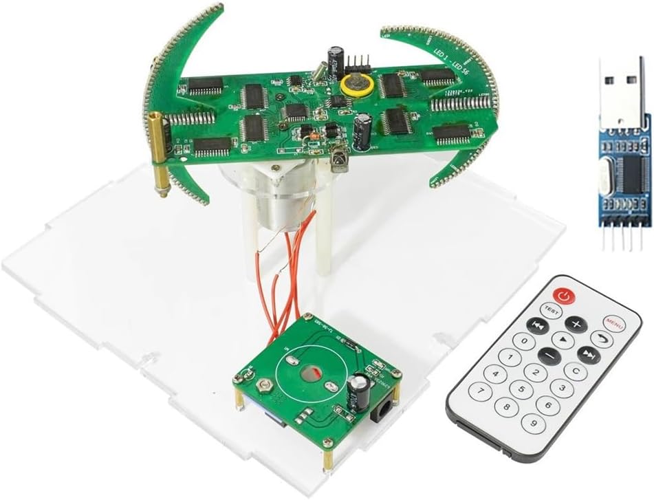
Figure 4.1: An example of the fully assembled Giwnhvx Dual Spherical Rotating LED Kit, showing the main control board, LED panels, acrylic base, remote control, and USB downloader.

Figure 4.2: A side view of the assembled LED kit, highlighting the rotating mechanism and the arrangement of the LED panels.
5. Operating Instructions
The Giwnhvx Dual Spherical Rotating LED Kit is operated primarily via the included remote control. Ensure the kit is powered on (DC 5V) before attempting to use the remote.
5.1 Remote Control Functions

Figure 5.1: Remote control layout with descriptions for each button's function, including power, menu, test, navigation, and numerical inputs for various display modes.
- Power Button (Red): Turns the device on or off.
- MENU Button: Accesses the main menu or cycles through display modes.
- TEST Button: Initiates a self-test sequence for LEDs and rotation.
- '+' / '-' Buttons: Adjusts parameters such as clock time, display speed, or brightness depending on the active mode.
- Navigation Buttons (Left/Right/Up/Down): Used for navigating menus or adjusting specific settings.
- Number Buttons (0-9): Selects specific display effects, clock modes, or enters numerical values.
- 'C' Button: Confirms selections or clears current input.
- Return/Back Button: Returns to the previous menu or setting.
Refer to the specific remote control diagram (Figure 5.1) for detailed button functions related to clock reset, digital clock adjustments, stereo display words, animation effects, and stereoscopic printing effects.
5.2 Display Modes and Customization
The kit supports various display modes, including:
- Digital Clock Mode: Displays time. Can be adjusted using '+' and '-' buttons.
- Analog Clock Simulation: Displays time in an analog format.
- Text Display: Capable of displaying up to 60 Chinese or 100 English characters. Text can be uploaded via the downloader.
- Stereo Display Word: Specific pre-programmed word displays.
- Stereo Animation Effects: Various dynamic visual patterns.
- Stereoscopic Printing Effect: Creates a 3D-like visual impression.
To upload custom text or firmware updates, connect the provided downloader to your computer and the kit. Use the accompanying software (not included in this manual, typically provided with the kit or available for download) to manage content.

Figure 5.2: The LED kit in operation, displaying a complex spherical pattern using blue LEDs, demonstrating its visual capabilities.

Figure 5.3: The LED kit in operation, showcasing a dynamic display with both blue and red LEDs creating a vibrant, rotating pattern.
6. Maintenance
Proper maintenance ensures the longevity and optimal performance of your LED kit.
- Cleaning: Use a soft, dry cloth to gently wipe the acrylic surfaces and electronic components. Avoid abrasive cleaners or solvents.
- Dust Removal: Periodically use compressed air to remove dust from the circuit boards and motor assembly to prevent overheating and ensure smooth operation.
- Component Inspection: Regularly inspect soldered joints for any signs of cracking or corrosion. Re-solder if necessary.
- Power Supply: Always use a stable DC 5V power supply. Incorrect voltage can damage components.
- Storage: When not in use, store the kit in a dry, dust-free environment away from direct sunlight and extreme temperatures.
7. Troubleshooting
This section addresses common issues you might encounter with your Giwnhvx Dual Spherical Rotating LED Kit.
| Problem | Possible Cause | Solution |
|---|---|---|
| Kit does not power on. | No power supply, incorrect voltage, faulty power connection, short circuit. | Verify DC 5V power supply connection. Check for loose wires or short circuits on the main board. |
| LEDs do not light up or display incorrectly. | Poor solder joints, incorrect LED polarity, faulty LED, incorrect firmware. | Inspect all LED solder joints. Ensure LEDs are installed with correct polarity. If individual LEDs are faulty, replace them. Re-upload firmware using the downloader. |
| Motor does not rotate. | Motor not connected, faulty motor, driver circuit issue, obstruction. | Check motor connections to the main board. Ensure no physical obstructions. Inspect motor driver components on the PCB. |
| Remote control not responding. | Dead battery, remote not pointed correctly, IR receiver blocked or faulty. | Replace remote control battery. Ensure clear line of sight to the IR receiver. Check IR receiver connections on the main board. |
| Custom text not displaying. | Incorrect upload procedure, software error, text format issue. | Ensure the downloader is correctly connected and the software is used as per its instructions. Verify text format compatibility. |
8. Support
For further assistance, technical support, or inquiries regarding replacement parts, please refer to the contact information provided by your retailer or the manufacturer, Giwnhvx. When contacting support, please have your product model number (500435433A1) and a detailed description of the issue ready.