
1. Introduction
This manual provides comprehensive instructions for the safe and efficient operation of your Jopix AT-5555N II Amateur Radio Station. This complete transceiver is designed for amateur radio enthusiasts, supporting AM, FM, and SSB modes across the 10M CW TRX 28-29.7 MHz frequency range. Please read this manual thoroughly before operating the device to ensure proper usage and to maximize its performance.
Key features include:
- Complete transceiver for AM, FM, SSB frequencies, ideal for 10M CW TRX 28-29.7 MHz.
- Various operating modes including AM, FM, SSB, VOX, and Roger Beep for flexible communication.
- Advanced functions allowing effective communication on amateur radio frequencies.
- Operates with a 13.8V power supply, suitable for amateur radio station setups.
2. Safety Information
Always observe the following safety precautions to prevent injury or damage to the radio station:
- Power Supply: Use only a stable 13.8V DC power supply. Ensure correct polarity when connecting the power cable. Incorrect voltage or polarity can damage the unit.
- Antenna: Connect a properly tuned antenna before transmitting. Transmitting without an antenna or with a mismatched antenna can cause damage to the transceiver's final amplifier.
- Ventilation: Ensure adequate ventilation around the unit to prevent overheating. Do not block ventilation slots.
- Environment: Do not expose the unit to rain, moisture, direct sunlight, or extreme temperatures. Avoid dusty environments.
- Servicing: Do not attempt to open or service the unit yourself. Refer all servicing to qualified personnel.
- Interference: This device may cause radio interference. Take appropriate measures to mitigate such interference.
3. Package Contents
Verify that all items listed below are included in your package:
- Jopix AT-5555N II Radio Station
- Microphone
- Microphone Holder
- Station Mounting Bracket
- Power Cable
- Programming Cable

Figure 3.1: The Jopix AT-5555N II radio station with its included microphone.

Figure 3.2: The power cable supplied with the radio station.
4. Product Components and Controls
4.1 Front Panel

Figure 4.1: Front panel of the Jopix AT-5555N II.
The front panel features the multi-function backlight display and various controls for operation:
- Display: Multi-function backlight display showing frequency, mode, S-meter, and other operational indicators.
- FRQ/REP Button: Frequency adjustment and repeater function.
- BAND/TONE Button: Band selection and tone control.
- AFG/PWR Knob: Audio Gain and Power output adjustment.
- VOL Knob: Volume control.
- MENU Button: Accesses the main menu for settings.
- MODE Button: Selects operating modes (AM, FM, LSB, USB, CW, PA).
- DW/TSQ Button: Dual Watch and Tone Squelch control.
- RB/BEEP Button: Roger Beep and Key Tone control.
- NB/HCUT Button: Noise Blanker and HI-CUT filter activation.
- SCAN/SKIP Button: Channel scan and skip function.
- MEM/STOR Button: Memory recall and store function.
- EMG/LOCK Button: Emergency channel access and keypad lock.
- CLAR/SQ Knob: Clarifier and Squelch control.
- CH Knob: Channel selection.
4.2 Rear Panel

Figure 4.2: Rear panel of the Jopix AT-5555N II.
The rear panel provides essential connections for the radio's operation:
- Antenna Connector: Standard coaxial connector for connecting an external antenna.
- Power Input: 13.8V DC power input.
- External Speaker Jack: 3.5 mm jack for connecting an additional external speaker.
- PA Connection: Output for connecting to a Public Address (PA) system.
- Programming Connection: Port for connecting the programming cable to a computer.
4.3 Microphone
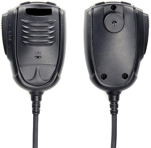
Figure 4.3: Front and back view of the microphone.
The microphone connects to the front panel via an RJ-45 connector and includes a Push-To-Talk (PTT) button for transmission.
5. Setup
5.1 Mounting the Radio
Use the provided station mounting bracket to securely install the radio in a suitable location. Ensure the location allows for adequate ventilation and easy access to controls and connections.
5.2 Power Connection
- Ensure the radio is turned off and the power supply is disconnected.
- Connect the supplied power cable to the 13.8V DC power input on the rear panel of the radio.
- Connect the other end of the power cable to a stable 13.8V DC power source, observing correct polarity (red to positive, black to negative).
5.3 Antenna Connection
Connect a properly tuned 10-meter band antenna to the antenna connector on the rear panel. Use a high-quality coaxial cable with appropriate connectors. Warning: Do not transmit without an antenna connected, as this can severely damage the radio.
5.4 Microphone Connection
Plug the RJ-45 connector of the microphone into the corresponding jack on the front panel of the radio. Secure the microphone using the provided microphone holder.
6. Operating Instructions
6.1 Basic Operation
- Power On: Turn the VOL knob clockwise to power on the radio. Adjust the volume to a comfortable level.
- Squelch Adjustment: Rotate the SQ knob clockwise until the background noise disappears. This sets the squelch level.
- Channel Selection: Use the CH knob to select the desired operating channel.
- Mode Selection: Press the MODE button to cycle through available modes: AM, FM, LSB, USB, CW, PA.
- Frequency Adjustment: Use the FRQ knob for fine-tuning the frequency within the selected channel or band.
- Transmission: Press and hold the PTT button on the microphone to transmit. Release to receive.
6.2 Advanced Features
- Dual Watch (DW): Allows monitoring of two channels simultaneously. Activate using the DW button.
- Channel Scan: Automatically scans through active channels. Activate using the SCAN button.
- RF Gain: Adjusts the receiver's sensitivity to incoming signals. Control with the RFG knob.
- Automatic Squelch (ASQ): Provides automatic squelch control for hands-free operation.
- Keypad Lock: Prevents accidental changes to settings. Activate using the LOCK function.
- Noise Filters (NB, ANL, HI-CUT): Reduce various types of noise. Activate using the NB/HCUT button.
- Roger Beep: Transmits a short tone at the end of your transmission. Activate using the RB button.
- Clarifier: Fine-tunes the receive frequency for SSB signals. Use the CLAR knob.
- Emergency Channel (9/19): Quick access to emergency channels.
- Channel Memory: Store and recall up to 100 channels. Use MEM/STOR buttons.
- RF Power Control: Adjusts the transmission power output.
- Echo Function: Adds an echo effect to your transmitted audio.
- SWR Meter: Displays the Standing Wave Ratio of your antenna system.
- VOX: Voice-activated transmission, allowing hands-free operation.
- S-meter: Indicates the strength of received signals.
- TOT (Time Out Timer): Limits continuous transmission time to prevent overheating.
- Talkback: Allows you to hear your own voice through the speaker during transmission.
- Key Tone: Audible feedback for button presses.
- CTCSS/DCS: Sub-audible tones for selective calling.
7. Maintenance
Proper maintenance ensures the longevity and optimal performance of your Jopix AT-5555N II radio station.
- Cleaning: Use a soft, dry cloth to clean the exterior of the unit. Do not use abrasive cleaners or solvents.
- Connections: Periodically check all cable connections (power, antenna, microphone) to ensure they are secure and free from corrosion.
- Ventilation: Ensure that the ventilation slots on the unit are clear of dust and debris to prevent overheating.
- Storage: When not in use for extended periods, store the radio in a cool, dry place, away from direct sunlight and extreme temperatures.
8. Troubleshooting
This section addresses common issues you might encounter with your radio station. If the problem persists after following these steps, contact customer support.
| Problem | Possible Cause | Solution |
|---|---|---|
| No power | Power cable disconnected; Incorrect polarity; Blown fuse in power cable or supply. | Check power cable connection; Verify correct polarity; Replace fuse if necessary. |
| No transmission (TX) | Antenna not connected; Microphone not connected; PTT button faulty; SWR too high. | Connect antenna; Connect microphone; Test PTT button; Check antenna SWR. |
| No reception (RX) | Squelch set too high; Volume too low; Antenna disconnected. | Adjust SQ knob counter-clockwise; Increase VOL; Check antenna connection. |
| Poor audio quality | Microphone issue; Noise filters active; Incorrect mode. | Check microphone connection; Disable NB/ANL/HI-CUT; Ensure correct operating mode. |
| Display not working | Power issue; Display settings. | Check power supply; Refer to menu settings for display brightness/backlight. |
9. Specifications
Detailed technical specifications for the Jopix AT-5555N II Amateur Radio Station:
| Feature | Description |
|---|---|
| Model | AT5555N-II |
| Frequency Range | 28,000 - 29,700 MHz (Programmable) |
| Band Type | PA - CW - AM - FM - LSB - USB |
| Channels | 60 programmable channels in each band, 100 memory channels |
| Power Supply | 13.8 V DC |
| Dimensions (W x H x D) | 200 x 180 x 60 mm (7.87 x 7.09 x 2.36 inches) |
| Weight | 1.768 kg (3.9 lbs) |
| Microphone Type | RJ-45 |
| Sensitivity (20dB SINAD) | 1.0 µV AM/FM; 0.25 µV SSB |
| Sensitivity (10dB S+N/N) | SSB: 0.25 µV, AM: 1.0 µV |
| Speaker Audio Power | 3 W @ 8 Ω |
| Transmission Power | AM: 60W / FM: 50W / SSB: 60W (PEP) |
| Operating Temperature | -20°C to +55°C (-4°F to +131°F) |
| Special Features | Dual Watch, Channel Scan, RF Gain, ASQ, Keypad Lock, NB, ANL, HI-CUT, Roger Beep, Clarifier, Frequency Step Adjustment, Emergency Channel (9/19), Channel Memory (100), RF Power Control, Echo Function, SWR Meter, VOX, S-meter, TOT, Talkback, Key Tone, CTCSS/DCS, Multi-function Backlight Display |
| External Connections | External Speaker (3.5mm), PA Output, Programming Port |
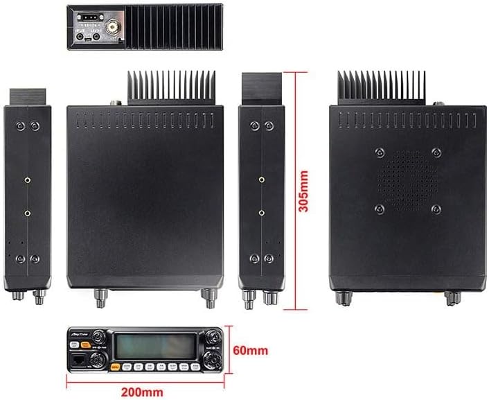
Figure 9.1: Dimensional overview of the Jopix AT-5555N II radio.
10. Warranty and Support
For specific warranty terms and conditions, please refer to the documentation provided at the time of purchase or contact your retailer. Warranty coverage typically varies by region and seller.
For technical support, troubleshooting assistance beyond this manual, or inquiries regarding parts and service, please contact the manufacturer or your authorized dealer. Keep your purchase receipt and product model number (AT-5555N II) readily available when seeking support.
You can often find additional resources, firmware updates, and FAQs on the official Jopix website or through authorized distributors.