
PowMr f565c90e-34e7-49b0-b3e0-097efdbc8a51
Contents
PowMr 2400W Solar Inverter & 24V Battery Equalizer User Manual
Model: f565c90e-34e7-49b0-b3e0-097efdbc8a51
1. Introduction
This manual provides detailed instructions for the installation, operation, and maintenance of your PowMr 2400W Solar Inverter and PowMr 24V Battery Equalizer. Please read this manual thoroughly before installation and use to ensure proper operation and safety.
The PowMr 2400W Solar Inverter is a pure sine wave inverter designed to convert 24V DC power to 110V/120V AC power, featuring a 50A PWM charge controller. The PowMr 24V Battery Equalizer is designed to maintain charge and discharge balance among batteries connected in series or parallel, extending battery life.

Figure 1.1: PowMr 2400W Solar Inverter and 24V Battery Equalizer.
2. Safety Information
Please observe the following safety precautions during installation and operation:
- Read all instructions and cautionary markings on the unit and in this manual before operating.
- Do not disassemble the unit. Refer servicing to qualified personnel.
- Ensure all wiring is correctly connected and terminals are secure to prevent loose connections that can cause overheating.
- Install the unit in a well-ventilated area, away from flammable materials and direct sunlight.
- Wear appropriate personal protective equipment (PPE) such as insulated gloves and eye protection during installation.
- Disconnect all power sources before performing any maintenance or wiring.
- This device is designed for indoor use. Avoid exposure to rain, snow, or excessive moisture.
3. Package Contents
Verify that all items are included in your package:
- 1 x PowMr 2400W Solar Inverter
- 1 x PowMr 24V Battery Equalizer
- 1 x User Manual (this document)
- Necessary connection cables and accessories (as supplied by manufacturer)
4. Product Features
4.1 PowMr 2400W Solar Inverter
- 2400W Pure Sine Wave Inverter: Converts 24V DC to 110V/120V AC.
- Integrated 50A PWM Charge Controller: High charging efficiency up to 95%.
- Advanced SPWM Technology and Dual Closed-Loop Control.
- Compatible with 24V Lead-Acid batteries (sealed, AGM, Gel, Flooded).
- Multiple Charging Modes: Solar First, Utility First, Solar and Utility, Only Solar.
- Three Load Output Working Modes: Utility First, Solar First, SBU First.
- Intelligent Protection: Reverse polarity protection, Low Voltage Disconnect.

Figure 4.1: Inverter dimensions and key specifications.

Figure 4.2: Inverter compatibility with various battery types.

Figure 4.3: Inverter charging and output mode options.
4.2 PowMr 24V Battery Equalizer
- Maintains charge and discharge balance between batteries in series or parallel.
- Extends battery service life.
- Maximum compensation current: 5A.
- Suitable for 24V or higher voltage battery groups (multiple equalizers can be connected in parallel).
- Reverse polarity protection.

Figure 4.4: Battery Equalizer key benefits.
5. Installation and Setup
5.1 PowMr 2400W Solar Inverter Installation
The inverter should be installed in a clean, dry, and well-ventilated indoor environment. Ensure adequate clearance around the unit for proper airflow.
- Mounting: Securely mount the inverter to a vertical surface using appropriate fasteners.
- Battery Connection: Connect the 24V battery bank to the inverter's battery terminals. Ensure correct polarity (positive to positive, negative to negative).
- PV Array Connection: Connect your solar panels to the PV input terminals. Ensure the PV array open circuit voltage does not exceed 80V.
- AC Output Connection: Connect your AC loads (home appliances) to the AC output terminals.
- Utility/Generator Connection (Optional): If using utility or generator input, connect it to the designated AC input terminals.

Figure 5.1: Typical system application diagram for the solar inverter.
Important: Always connect the battery first, then the solar panels, and finally the AC loads. Disconnect in reverse order.
5.2 PowMr 24V Battery Equalizer Installation
The battery equalizer is designed to balance the voltage of batteries connected in series. For a 24V system, it connects across two 12V batteries.
- Red cable: Connect to Battery B positive (+) pole.
- Black cable: Connect to Battery A negative (-) pole.
- White cable: Connect to the pole which connects Battery A and Battery B in series (the center connection).
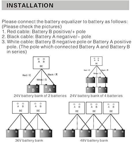
Figure 5.2: Battery Equalizer connection diagrams for various battery bank configurations.
For battery banks with voltages higher than 24V (e.g., 36V or 48V), multiple 24V equalizers can be connected in parallel as shown in Figure 5.2 to ensure proper balancing across all series-connected batteries.
6. Operating Instructions
6.1 PowMr 2400W Solar Inverter Operation
After successful installation, power on the inverter. The LCD display will show system status, input/output voltages, charging current, and other parameters. Refer to the inverter's specific display interface for detailed readings.
Charging Modes: The inverter supports four charging modes, configurable via the inverter's settings:
- Solar First: Prioritizes solar power for charging.
- Utility First: Prioritizes utility power for charging.
- Solar and Utility: Uses both solar and utility power for charging.
- Only Solar: Charges exclusively from solar power.
Load Output Working Modes: The inverter offers three modes for powering loads:
- Utility First: Prioritizes utility power to supply loads.
- Solar First: Prioritizes solar power to supply loads.
- SBU First (Solar-Battery-Utility): Prioritizes solar, then battery, then utility for loads.
Consult the inverter's on-screen menu or dedicated buttons for navigating and setting these modes.
6.2 PowMr 24V Battery Equalizer Operation
Once connected, the battery equalizer operates automatically. It continuously monitors the voltage of each battery in the series and draws current from the higher voltage battery to charge the lower voltage battery until they are balanced. This process helps prevent overcharging and undercharging of individual batteries, which can lead to premature battery failure.
LED Indicators: The equalizer typically features LED indicators to show its operational status. Refer to the technical data section for specific LED behavior.
7. Technical Specifications
7.1 PowMr 2400W Solar Inverter Specifications
| Parameter | Value |
|---|---|
| Rated Output Power | 2400W |
| Rated Output Voltage | 110Vac ±10% / 120Vac |
| DC Input Voltage | 24Vdc |
| Max. PV Array Open Circuit Voltage | 80Vdc |
| Max Solar Charge Current (PWM) | 50A |
| Hybrid Charging Max Charger Current | 50A |
| PWM Voltage Range | 30~32Vdc |
| Battery Compatibility | 24V Lead-Acid (Seal, AGM, Gel, Flooded) |
| Dimensions (approx.) | 13.97in (H) x 10.7in (W) x 3.97in (D) |
| Weight (approx.) | 6.9KG |
7.2 PowMr 24V Battery Equalizer Specifications
| Parameter | Value |
|---|---|
| Battery Nominal Voltage | 2 x 12V (for 24V system) |
| Optimizing Current | 0-5A |
| Quiescent Current | <3mA |
| Dimensions | 70 x 70 x 27 mm |
| Protection | Reverse polarity protection |
| Low Voltage Disconnect | 10V |
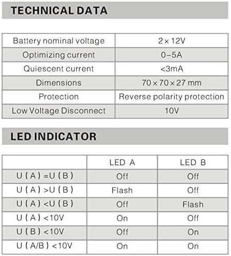
Figure 7.1: Battery Equalizer technical data and LED indicator behavior.
LED Indicator Behavior:
- U(A) = U(B): LED A Off, LED B Off (Balanced)
- U(A) > U(B): LED A Flash, LED B Off (Battery A discharging to Battery B)
- U(A) < U(B): LED A Off, LED B Flash (Battery B discharging to Battery A)
- U(A) < 10V: LED A On, LED B Off (Battery A low voltage)
- U(B) < 10V: LED A Off, LED B On (Battery B low voltage)
- U(A/B) < 10V: LED A On, LED B On (Both batteries low voltage)
8. Maintenance
Regular maintenance ensures optimal performance and longevity of your PowMr solar inverter and battery equalizer system.
- Cleanliness: Keep the inverter and equalizer clean and free from dust. Use a dry cloth to wipe surfaces. Ensure ventilation openings are not blocked.
- Connections: Periodically check all electrical connections for tightness. Loose connections can cause overheating and damage.
- Battery Health: Monitor battery voltage and health regularly. The battery equalizer helps, but overall battery health is crucial for system performance.
- Environment: Ensure the installation environment remains within specified temperature and humidity ranges.
9. Troubleshooting
This section provides solutions to common issues. If the problem persists, contact PowMr customer support.
| Problem | Possible Cause | Solution |
|---|---|---|
| Inverter not turning on | No battery connection; Low battery voltage; Blown fuse. | Check battery connections; Charge battery; Check and replace fuse if necessary. |
| No AC output | Overload; Over-temperature; Battery low voltage. | Reduce load; Allow inverter to cool down; Charge battery. |
| Battery Equalizer LEDs off (when batteries are unbalanced) | Incorrect wiring; Equalizer fault. | Verify wiring according to Figure 5.2; Contact support if wiring is correct. |
| Battery Equalizer not balancing effectively | Excessive voltage difference; Equalizer capacity exceeded. | Ensure initial battery voltages are not severely disparate; Consider adding another equalizer for larger imbalances or higher current needs. |
10. Warranty and Support
PowMr products are designed for reliability and performance. For warranty information, technical support, or service inquiries, please contact PowMr customer service through their official website or the retailer where you purchased the product.
Please have your product model number (f565c90e-34e7-49b0-b3e0-097efdbc8a51) and purchase details ready when contacting support.
Visit the official PowMr Store for more information: PowMr Store on Amazon
Ask a question about this manual
Ask about setup, troubleshooting, compatibility, parts, safety, or missing instructions. Manuals+ will review the question and use this page’s manual context to help answer it.