
KORAD KA3005D-23
KORAD KA3005D-23 Precision Variable Adjustable 30V, 5A DC Linear Power Supply - User Manual
Model: KA3005D-23
1. Introduction
The KORAD KA3005D-23 is a heavy-duty, single-channel linear DC power supply designed for precision applications in labs, colleges, and production environments. It offers continuously adjustable voltage and current settings with low ripple and noise, high reliability, and high accuracy. This manual provides detailed instructions for the safe and efficient operation of your KA3005D-23 power supply.
This unit features a bright, easy-to-read 4-digit LED screen displaying voltage, current, and power values. It also includes four memory locations (M1-M4) for storing frequently used settings, and multiple protection features such as over-voltage and over-current protection.
2. Safety Information
Please read all safety instructions carefully before operating the device. Failure to comply with these instructions may result in electric shock, fire, or damage to the device.
- Ensure the power supply is connected to a grounded outlet.
- Do not operate the device in wet or damp conditions.
- Do not open the casing. There are no user-serviceable parts inside. Refer all servicing to qualified personnel.
- Verify the input voltage selector switch on the rear panel is set correctly for your local power grid (110V or 220V) before connecting to AC power.
- Always turn off the output and disconnect power before making or changing connections to the output terminals.
- Avoid short-circuiting the output terminals for extended periods, even with protection features enabled.
- Use appropriate test leads rated for the voltage and current levels you will be working with.
3. Unit Features
The KORAD KA3005D-23 is equipped with several features to enhance its functionality and user experience.

Figure 3.1: Unit Features Overview. This image highlights the key features of the KORAD KA3005D-23 power supply, including its power and protection mechanisms, memory settings, bright 4-digit LED display, and switchable power input.
3.1 Power & Protection
- 30V/5A Benchtop Supply: Provides a stable and adjustable DC power source.
- Built-in Over-Current Protection (OCP): Automatically limits current to prevent damage to the connected circuit.
- Built-in Over-Voltage Protection (OVP): Prevents output voltage from exceeding a set limit, protecting sensitive components.
- Dedicated On/Off Button: Controls the unit's output, allowing for safe connection and disconnection of loads.
3.2 Memory Settings (M1-M4)
- Four dedicated memory locations allow users to store and recall frequently used voltage and current settings, streamlining repetitive tasks.
3.3 Bright 4-Digit LED Display
- Provides a precise and legible readout of voltage, current, and active settings from various angles.
3.4 Switchable Power Input
- Easily switchable between 110V and 220V on the rear panel to accommodate different regional power standards.
4. Panel Overview
Familiarize yourself with the front and rear panels of the KORAD KA3005D-23 power supply.
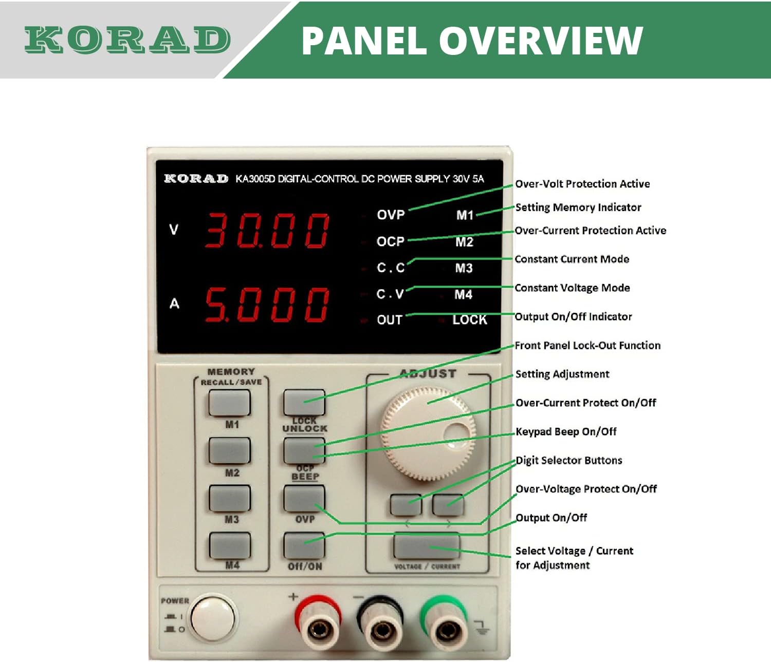
Figure 4.1: Front Panel Layout. This image provides a detailed view of the front panel, labeling all indicators, buttons, and controls for easy identification and understanding.
4.1 Front Panel Controls and Indicators
| Label/Indicator | Description |
|---|---|
| V Display | 4-digit LED display for output voltage. |
| A Display | 4-digit LED display for output current. |
| OVP Indicator | Illuminates when Over-Voltage Protection is active. |
| OCP Indicator | Illuminates when Over-Current Protection is active. |
| C.C Indicator | Illuminates when the unit is operating in Constant Current mode. |
| C.V Indicator | Illuminates when the unit is operating in Constant Voltage mode. |
| OUT Indicator | Illuminates when the output is active. |
| LOCK Indicator | Illuminates when the front panel controls are locked. |
| M1-M4 Buttons | Memory recall/save buttons for preset voltage and current settings. |
| LOCK/UNLOCK Button | Press and hold to lock or unlock the front panel controls. |
| BEEP Button | Toggles the keypad beep sound on/off. |
| OCP Button | Toggles Over-Current Protection on/off. |
| OVP Button | Toggles Over-Voltage Protection on/off. |
| On/Off Button | Activates or deactivates the power output to the terminals. |
| Adjust Knob | Rotary encoder for adjusting voltage or current values. |
| Left/Right Buttons (< / >) | Selects the digit to be adjusted by the Adjust Knob. |
| Voltage/Current Button | Toggles between voltage and current adjustment modes. |
| Output Terminals | Positive (+), Negative (-), and Ground (GND) terminals for connecting loads. |
| Power Button | Main power switch for the unit. |
4.2 Rear Panel Overview

Figure 4.2: Rear Panel Input Voltage Selector. This image shows the rear panel of the power supply, highlighting the AC power input, the voltage selector switch (110V/220V), and the cooling fan vent.
- AC Power Input: Standard IEC C14 inlet for connecting the power cord.
- Voltage Selector Switch: Allows selection between 110V and 220V AC input. Ensure this is set correctly before connecting to mains power.
- Cooling Fan: Intelligent temperature-controlled fan for efficient heat dissipation.
- USB Port: For PC connectivity and software control (if applicable).
5. Setup
- Unpacking and Inspection: Carefully remove the power supply from its packaging. Inspect the unit for any signs of physical damage. If damage is found, contact your supplier immediately.
- Input Voltage Selection: Before connecting the power cord, locate the voltage selector switch on the rear panel (refer to Figure 4.2). Ensure it is set to match your local AC mains voltage (110V or 220V). Incorrect setting can damage the unit.
- Power Connection: Connect the provided AC power cord to the AC power input on the rear panel and then to a grounded wall outlet.
- Initial Power On: Press the main Power button on the front panel. The display should illuminate.
- Output Terminal Connections: Connect your load to the output terminals (+, -, GND) using appropriate test leads. Ensure proper polarity.

Figure 5.1: Power Supply with Test Leads. This image shows the KORAD KA3005D-23 power supply along with the included test leads, demonstrating how they connect to the output terminals.
6. Operating Instructions
6.1 Setting Voltage and Current
- Select Adjustment Mode: Press the Voltage/Current button to toggle between voltage (V) and current (A) adjustment modes. The corresponding display will show the value to be set.
- Select Digit: Use the < and > buttons to select the digit you wish to adjust. The selected digit will blink.
- Adjust Value: Rotate the Adjust Knob clockwise to increase the value and counter-clockwise to decrease it.
- Activate Output: Once the desired voltage and current limit are set, press the On/Off button to activate the output. The OUT indicator will illuminate.
6.2 Memory Functions (M1-M4)
- Saving Settings: Set the desired voltage and current. Press and hold one of the M1-M4 buttons for approximately 2 seconds until a beep confirms the setting is saved.
- Recalling Settings: Briefly press one of the M1-M4 buttons. The stored voltage and current values will be loaded. Note that recalling a setting does not automatically activate the output; you must press the On/Off button.
6.3 Protection Features (OCP, OVP)
- Over-Current Protection (OCP): Press the OCP button to enable or disable this feature. When enabled, if the output current exceeds the set limit, the output will shut down to protect the load and the power supply. The OCP indicator will illuminate. To reset, clear the fault condition and press the On/Off button.
- Over-Voltage Protection (OVP): Press the OVP button to enable or disable this feature. When enabled, if the output voltage exceeds the set limit, the output will shut down. The OVP indicator will illuminate. To reset, clear the fault condition and press the On/Off button.
6.4 Keyboard Lock Function
- To prevent accidental changes to settings, press and hold the LOCK/UNLOCK button for approximately 2 seconds. The LOCK indicator will illuminate, and all front panel controls will be disabled.
- To unlock, press and hold the LOCK/UNLOCK button again for 2 seconds. The LOCK indicator will turn off.
7. Maintenance
- Cleaning: Disconnect the power supply from the mains before cleaning. Use a soft, dry cloth to wipe the exterior. Do not use abrasive cleaners or solvents.
- Ventilation: Ensure the cooling fan vents on the rear panel are clear of obstructions to allow for proper airflow.
- Storage: When not in use for extended periods, store the unit in a dry, dust-free environment.
- Fuse Replacement: If the unit does not power on, check the fuse located near the AC input on the rear panel. Replace only with a fuse of the same type and rating (e.g., 5A 250V for 110V input, 3A 250V for 220V input). Refer to the fuse holder for specific ratings.
8. Troubleshooting
| Problem | Possible Cause | Solution |
|---|---|---|
| Unit does not power on. | No AC power; Blown fuse; Incorrect voltage selector setting. | Check power cord connection and wall outlet. Replace fuse if blown. Verify voltage selector switch is set correctly. |
| No output voltage/current. | Output is off; OCP/OVP triggered; Incorrect settings. | Press the On/Off button to activate output. Check OCP/OVP indicators and clear fault. Verify voltage/current settings. |
| Output voltage/current is unstable. | Poor load connection; Overheating; Faulty test leads. | Ensure secure connections. Check for proper ventilation. Replace test leads if damaged. |
| Front panel controls are unresponsive. | Keyboard lock is active. | Press and hold the LOCK/UNLOCK button for 2 seconds to disable the lock. |
| Fan is noisy or constantly running. | Normal operation under load; Obstructed vents. | The fan is temperature-controlled and will run as needed. Ensure vents are clear. |
9. Specifications

Figure 9.1: Technical Specifications Table. This image provides a comprehensive table of the KORAD KA3005D-23's electrical specifications, including voltage and current ranges, load regulation, and ripple.

Figure 9.2: Unit Dimensions. This image illustrates the physical dimensions and weight of the KORAD KA3005D-23 power supply.
| Parameter | Value |
|---|---|
| Voltage Range | 0-30V |
| Current Range | 0-5A |
| Load Regulation (Voltage) | ≤0.01% + 2mV |
| Load Regulation (Current) | ≤0.1% + 10mA |
| Line Regulation (Voltage) | ≤0.01% + 3mV |
| Line Regulation (Current) | ≤0.1% + 3mA |
| Setup Resolution (Voltage) | 10mV |
| Setup Resolution (Current) | 1mA |
| Setup Accuracy (25°C ± 5°C) (Voltage) | ≤0.5% + 20mV |
| Setup Accuracy (25°C ± 5°C) (Current) | ≤0.5% + 10mA |
| Ripple (20-20M) (Voltage) | ≤2mVrms |
| Ripple (20-20M) (Current) | ≤2mVrms |
| Temperature Coefficient (Voltage) | ≤150ppm |
| Temperature Coefficient (Current) | ≤150ppm |
| Read Back Resolution (Voltage) | 10mV |
| Read Back Resolution (Current) | 1mA |
| Read Back Temp. Coefficient (Voltage) | ≤150ppm |
| Read Back Temp. Coefficient (Current) | ≤150ppm |
| Reaction Time (Voltage Rise) | ≤100mS |
| Reaction Time (Voltage Drop) | ≤100mS |
| Interface | Non-Programmable Interface |
| Weight | 9.52 Lbs / 4.32 Kg |
| Dimensions (W x H x D) | 100mm (W) x 156mm (H) x 260mm (D) |
Note: Specifications are subject to change without notice. For the most up-to-date information, please refer to the manufacturer's official website.
10. Warranty and Support
Specific warranty terms and conditions for the KORAD KA3005D-23 power supply are typically provided with the product packaging or available on the manufacturer's official website. Please refer to these resources for detailed information regarding warranty coverage, duration, and claims procedures.
For technical support, service, or inquiries about replacement parts, please contact KORAD customer service through their official channels. Keep your purchase receipt and product serial number handy when seeking support.
Ask a question about this manual
Ask about setup, troubleshooting, compatibility, parts, safety, or missing instructions. Manuals+ will review the question and use this page’s manual context to help answer it.