
GODIYMODULES c32342e9-1c6f-4afc-91b5-d6ac139d7760
GODIYMODULES 2 PCS Motor Driver Module Instruction Manual
Model: c32342e9-1c6f-4afc-91b5-d6ac139d7760
1. Introduction
This manual provides essential information for the safe and effective use of the GODIYMODULES 2 PCS Motor Driver Module. This module is a high-current H-bridge driver designed for controlling DC motors or semiconductor refrigeration units, supporting a voltage range of 5V to 15V DC and currents up to 50A.
Please read this manual thoroughly before installation and operation to ensure proper functionality and to prevent damage to the module or connected devices.
2. Key Features
- MOSFET high current (50A) H-bridge driver.
- Single chip PWM signal isolation for effective protection of microcontrollers.
- Supports motor reverse functionality.
- Two-way PWM input with a maximum frequency of 200kHz.
- Compatible with supply voltages from 5V to 15V DC.
- Clear power indicator for operational status.
3. Specifications
| Parameter | Value |
|---|---|
| Model Number | c32342e9-1c6f-4afc-91b5-d6ac139d7760 |
| Input Voltage Range | DC 5V to 15V |
| Maximum Current | 50 Amps (Peak) |
| PWM Frequency | Up to 200 kHz |
| Material | Semiconductor |
| Dimensions | 3.94 x 1.97 x 0.8 inches |
| Item Weight | 1.76 ounces |
Note: The 50A current rating is typically a peak or surge current. For continuous operation, it is recommended to stay within a lower average load, such as 10A or less, to prevent overheating and potential damage. Adequate heat dissipation is crucial for high current applications.
4. Package Contents
- 2 x GODIYMODULES Motor Driver Modules

5. Setup and Wiring
Before connecting the module, ensure all power sources are disconnected. Incorrect wiring can damage the module and connected components.
5.1 Module Overview
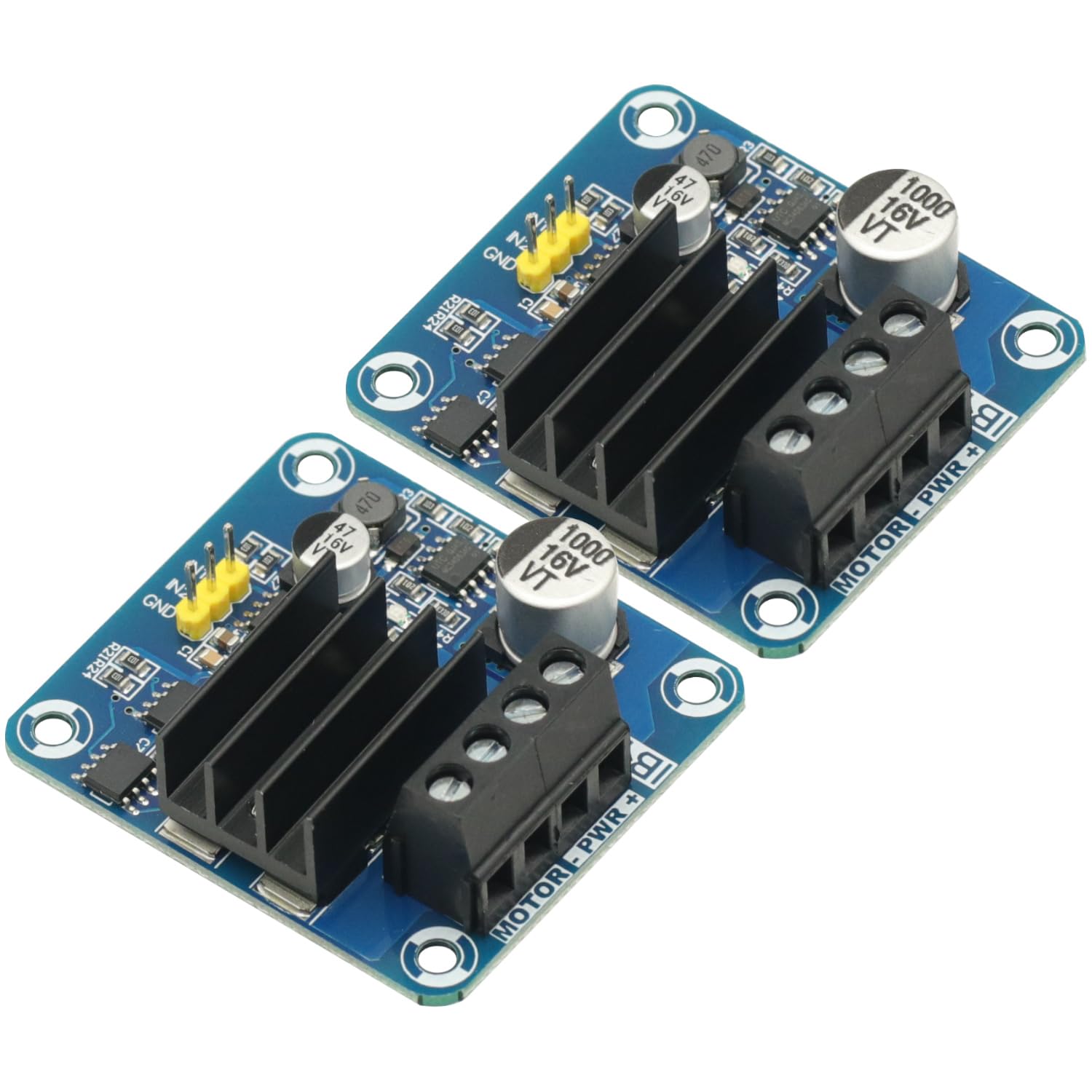

5.2 Wiring Diagram
Refer to the following diagram for proper connection of power, motor, and control signals.

5.3 Connection Steps
- Power Supply Connection: Connect your DC power supply (5V to 15V) to the "MOTOR-PWR+" terminal block. Ensure the positive (+) terminal of the power supply connects to the "+" screw terminal and the negative (-) terminal connects to the "-" screw terminal.
- Motor Connection: Connect your DC motor to the "MOTOR" screw terminals. The polarity here will determine the initial direction of rotation.
- Control Signal Connection: Connect your microcontroller or control source to the input pins:
- IN1: Input 1 for controlling motor direction/speed.
- IN2: Input 2 for controlling motor direction/speed.
- GND: Ground connection for the control signals, typically connected to the microcontroller's ground.
- Verify Connections: Double-check all connections for correct polarity and secure fastening before applying power.
6. Operating Instructions
The module uses two input signals (IN1 and IN2) to control the motor's direction and speed via PWM. The power indicator LED will illuminate when power is supplied to the module.
6.1 Motor Control Logic
| IN1 Signal | IN2 Signal | Motor Action |
|---|---|---|
| LOW (0V) | LOW (0V) | Motor Stop (Brake) |
| HIGH (3.3V-12V) | LOW (0V) | Motor Forward (Speed controlled by PWM on IN1) |
| LOW (0V) | HIGH (3.3V-12V) | Motor Reverse (Speed controlled by PWM on IN2) |
| HIGH (3.3V-12V) | HIGH (3.3V-12V) | Motor Stop (Brake) |
To control motor speed, apply a Pulse Width Modulation (PWM) signal to the active input (IN1 for forward, IN2 for reverse). The frequency of the PWM signal can be up to 200kHz.
The module is designed with signal isolation to protect the microcontroller from motor noise and voltage spikes.
7. Maintenance
The GODIYMODULES Motor Driver Module requires minimal maintenance. Follow these guidelines to ensure longevity and reliable operation:
- Keep Clean: Ensure the module is free from dust, dirt, and moisture. Use a soft, dry brush or compressed air for cleaning.
- Environmental Conditions: Operate the module within its specified temperature and humidity ranges. Avoid extreme conditions.
- Heat Management: For applications involving high continuous currents, ensure adequate airflow around the heatsinks to prevent overheating. Consider additional cooling if necessary.
- Connection Integrity: Periodically check all screw terminal connections to ensure they are tight and secure. Loose connections can lead to intermittent operation or arcing.
8. Troubleshooting
If you encounter issues with your motor driver module, refer to the following troubleshooting steps:
| Problem | Possible Cause | Solution |
|---|---|---|
| Module not powering on (Power LED off) | No power supply, incorrect polarity, faulty power supply, loose connections. |
|
| Motor does not move | Incorrect control signals, motor not connected, faulty motor, insufficient power, module damage. |
|
| Motor moves in wrong direction | Incorrect IN1/IN2 signal combination, motor polarity reversed. |
|
| Module gets excessively hot | Overcurrent, insufficient heat dissipation, short circuit. |
|
9. Warranty Information
Specific warranty details for GODIYMODULES products may vary. Please refer to the purchase documentation or contact your retailer for information regarding warranty coverage and terms.
This warranty typically covers defects in materials and workmanship under normal use. It does not cover damage caused by misuse, improper installation, unauthorized modification, or operation outside the specified parameters.
10. Customer Support
For technical assistance, questions, or support regarding your GODIYMODULES Motor Driver Module, please contact your point of purchase or visit the official GODIYMODULES website for contact information.
When contacting support, please have your product model number (c32342e9-1c6f-4afc-91b5-d6ac139d7760) and a detailed description of the issue ready.
Related documentsc32342e9-1c6f-4afc-91b5-d6ac139d7760

Ask a question about this manual
Ask about setup, troubleshooting, compatibility, parts, safety, or missing instructions. Manuals+ will review the question and use this page’s manual context to help answer it.