1. Safety Information
Please read and understand all safety instructions before operating the VOLTCRAFT PMM 6010-60. Failure to follow these instructions may result in electric shock, fire, or personal injury.
- This device is rated CAT II 600 V. Always adhere to the specified voltage and current limits.
- Ensure the device is properly grounded before use.
- Do not operate the device in wet or damp conditions.
- Inspect test leads and power cables for damage before each use. Replace any damaged components immediately.
- The device is equipped with overvoltage, overcurrent, and short-circuit protection. Do not attempt to bypass these safety features.
- Only qualified personnel should perform maintenance or repairs.
- Keep the ventilation openings clear to prevent overheating. The intelligent fan regulates speed based on temperature.
2. Product Overview
The VOLTCRAFT PMM 6010-60 is a versatile 2-in-1 device, combining a digital multimeter (DMM) with a programmable power supply. It is designed for accurate electrical measurements and providing stable power to external circuits.
2.1 Key Features
- Digital Multimeter: 60,000 counts, True RMS for AC voltage and current, measures DC voltage, resistance, diode, continuity, and capacitance.
- Adjustable Power Supply: Single output, 0-60 V output voltage, 0-10 A output current, maximum power 300 W.
- Display: 7.11 cm (2.8 inch) TFT-LC display for clear result visualization.
- Connectivity: USB 2.0 interface, SCPI compatible for remote control.
- Safety: CAT II 600 V rating, overvoltage, overcurrent, and short-circuit protection, temperature-controlled intelligent fan.
2.2 Device Components

Figure 1: Front Panel. This image shows the front panel of the VOLTCRAFT PMM 6010-60, featuring the TFT-LC display, control buttons (F1-F4, DISP, Mode, On/Off), rotary knob, input/output terminals for multimeter and power supply functions, and a 5V 1A USB port.
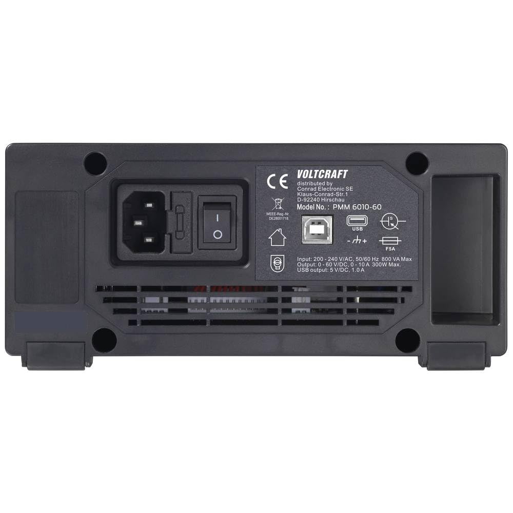
Figure 2: Rear Panel. This image displays the rear panel of the VOLTCRAFT PMM 6010-60, including the AC power input, power switch, USB port for PC connection, and ventilation grille.
2.3 Package Contents
Upon unpacking, ensure all the following items are present:
- VOLTCRAFT PMM 6010-60 Digital Multimeter and Power Supply
- USB Cable
- Power Cable
- Pair of Test Leads
- 250 V Fuse
- Software CD
- User Manual (this document)
- Safety Data Sheet

Figure 3: Device and Accessories. This image shows the VOLTCRAFT PMM 6010-60 unit alongside its included accessories: power cable, USB cable, and test leads.
3. Setup
3.1 Power Connection
- Ensure the device's power switch on the rear panel is in the OFF position.
- Connect the provided power cable to the AC input on the rear panel of the PMM 6010-60.
- Plug the other end of the power cable into a suitable grounded AC power outlet.
3.2 Connecting Test Leads
For multimeter functions, connect the test leads to the appropriate input jacks on the front panel. For power supply output, use the dedicated output terminals.
- Multimeter Inputs: Connect the red test lead to the VΩ/OVP or A terminal and the black test lead to the COM terminal. Ensure correct polarity for DC measurements.
- Power Supply Output: Connect your load to the red (+) and black (-) output terminals.
3.3 Software Installation (Optional)
The included software CD contains drivers and applications for PC communication. Insert the CD into your computer's optical drive and follow the on-screen instructions for installation. Connect the device to your PC using the provided USB cable to enable remote control via SCPI commands.
4. Operating Instructions
4.1 Powering On/Off
Flip the main power switch on the rear panel to the ON position. Then, press the On/Off button on the front panel to power on the device. Press it again to power off.
4.2 Multimeter Functions
Use the Mode button to cycle through different measurement functions. The display will indicate the active measurement mode.
- DC Voltage Measurement (V DC): Select DCV mode. Connect test leads in parallel with the circuit.
- AC Voltage Measurement (V AC True RMS): Select ACV mode. Connect test leads in parallel with the circuit. The True RMS feature ensures accurate readings regardless of waveform.
- Resistance Measurement (Ω): Select resistance mode. Ensure the circuit is de-energized. Connect test leads across the component.
- Diode Test: Select diode mode. Connect test leads across the diode.
- Continuity Test: Select continuity mode. Connect test leads across the circuit. An audible tone indicates continuity.
- Capacitance Measurement: Select capacitance mode. Ensure the capacitor is discharged before connecting test leads.
4.3 Power Supply Operation
The power supply section allows you to set precise voltage and current limits for your external circuits.
- Setting Voltage and Current: Use the rotary knob and the DISP or arrow buttons to select and adjust the desired output voltage (0-60 V) and current (0-10 A) limits. The display shows the set values.
- Enabling Output: Press the dedicated output ON/OFF button (often labeled with a power symbol or 'Output') to enable or disable the power supply output. The display will indicate if the output is active.
- Monitoring: The TFT-LC display continuously shows the actual output voltage and current delivered to the load.
4.4 USB Communication
Connect the device to a computer via the rear USB port. Using compatible software and SCPI commands, you can remotely control the power supply and retrieve multimeter readings.
5. Maintenance
5.1 Cleaning
To clean the device, disconnect it from all power sources and test circuits. Use a soft, damp cloth with a mild detergent. Do not use abrasive cleaners or solvents. Ensure the device is completely dry before re-connecting power.
5.2 Fuse Replacement
If the device fails to power on or a specific function stops working, check the fuse. Refer to the full user manual for detailed instructions on how to safely access and replace the 250 V fuse. Always replace with a fuse of the identical type and rating.
5.3 Ventilation
Ensure the ventilation openings on the rear and sides of the device are not obstructed. The intelligent fan system requires clear airflow to prevent overheating and maintain optimal performance.
6. Troubleshooting
This section provides basic troubleshooting steps for common issues. For more detailed diagnostics, please consult the comprehensive user manual provided on the software CD.
- Device does not power on: Check the power cable connection, the rear power switch, and the front panel On/Off button. Verify the fuse (see Section 5.2).
- No power supply output: Ensure the output is enabled via the front panel button. Check the set voltage and current limits. Verify connections to the load.
- Incorrect multimeter readings: Ensure test leads are correctly connected to the appropriate terminals for the selected measurement function. Verify the circuit is properly connected and within the device's measurement range.
- USB communication issues: Ensure the USB cable is securely connected to both the device and the PC. Verify that the correct drivers are installed on your computer.
7. Specifications
| Feature | Specification |
|---|---|
| Model Number | VC-15445405 |
| Display | 7.11 cm (2.8 inch) TFT-LC, 60,000 counts |
| Safety Rating | CAT II 600 V |
| Multimeter Functions | DCV, ACV (True RMS), Resistance, Diode, Continuity, Capacitance |
| Power Supply Outputs | 1 |
| Output Voltage | 0 - 60 V |
| Output Current | 0 - 10 A |
| Max. Output Power | 300 W |
| Resolution (V/A) | 10 mV / 1 mA |
| Interface | USB 2.0 (SCPI compatible) |
| Dimensions (L x W x H) | 18.5 x 20 x 9.2 cm |
| Weight | 1.2 kg |
8. Warranty and Support
VOLTCRAFT products are designed for quality and reliability. This product comes with a standard manufacturer's warranty. For specific warranty terms and conditions, please refer to the documentation included with your purchase or visit the official VOLTCRAFT website.
For technical support, troubleshooting assistance beyond this manual, or warranty claims, please contact your retailer or the VOLTCRAFT customer service department. Contact information can typically be found on the manufacturer's website or in your product packaging.


