1. Introduction
This manual provides detailed instructions for the installation, setup, and operation of the ACEIRMC Mach3 USB 100KHz 4-Axis Motion Controller Card. This board is designed to interface with CNC engraving machines, servo motors, and stepper motors, offering stable and reliable motion control.
Key Features:
- Supports 4-axis linkage for controlling four stepper or servo motor drives.
- Maximum step-pulse frequency of 100KHz.
- Requires external 24V DC power for isolated USB and external port stability.
- Features a 0-10V output port for spindle motor speed control via MACH3 software.
- Includes 4 general-purpose isolated relay drive output interfaces for controlling spindle start/stop, forward/reverse rotation, pumps, and other devices.
- Equipped with 4 general-purpose inputs for connecting limit switches, E-stop switches, probe switches, and home switches.
- Supports automatic probe tool, emergency input, limit switch, and electronic handwheel connection.

Image 1.1: The ACEIRMC Mach3 USB 100KHz 4-Axis Motion Controller Card with its included USB cable.
2. Package Contents
Verify that all items listed below are included in your package:
- 1 × USB CNC Controller Card
- 1 × USB cable
- 1 × CD (Software/Drivers)

Image 2.1: Contents of the package, including the controller card and USB cable.
3. Specifications
| Feature | Specification |
|---|---|
| Dimensions | 80 × 77 mm (3.15 × 3.03 inches) |
| Weight | 160 g (0.35 lb) |
| Input Voltage | 24 Volts DC (External) |
| Operating Temperature | 25 Degrees Celsius (Typical) |
| Max Step-Pulse Frequency | 100 KHz |
| Axis Support | 4-Axis Linkage |
| Output Ports | 4 General-Purpose Isolated Relay Drive Outputs, 0-10V Spindle Output |
| Input Ports | 4 General-Purpose Inputs (Limit, E-stop, Probe, Home) |

Image 3.1: Physical dimensions of the controller board and the USB cable length.
4. Setup
Follow these steps to properly set up your Mach3 USB Motion Controller Card.
4.1 Power Supply Connection
The motion controller requires an external 24V DC power supply. Connect the positive (+) terminal of your 24V DC power supply to the '24V' terminal on the board and the negative (-) terminal to the 'DCM' terminal. This external power ensures isolation between the USB and external ports, enhancing system stability.
4.2 USB Connection
Connect the provided USB cable from the USB port on the controller card to an available USB port on your computer (notebook or tablet PC). The board is designed for free-drive operation, simplifying configuration.
4.3 Motor and Input/Output Connections
Refer to the diagram below for connecting your stepper motor drives, servo drives, and various input/output devices.

Image 4.1: Detailed diagram of all connection points on the controller board.
- X, Y, Z, A-axis Drivers: Connect your stepper or servo motor drivers to the corresponding X, Y, Z, and A terminals.
- 4-Channel Output (OUT1-OUT4): These isolated relay drive outputs can control devices such as spindle start/stop, forward/reverse, and coolant pumps.
- 4-Channel Input (IN1-IN4): These general-purpose inputs are used for connecting various switches.
- Inverter Interface (0-10V): Use this output to control the spindle motor speed via MACH3 software.
- Handwheel Interface: Connect an electronic handwheel for manual control.
4.4 Input Device Connections
The board supports various input devices for enhanced control and safety:
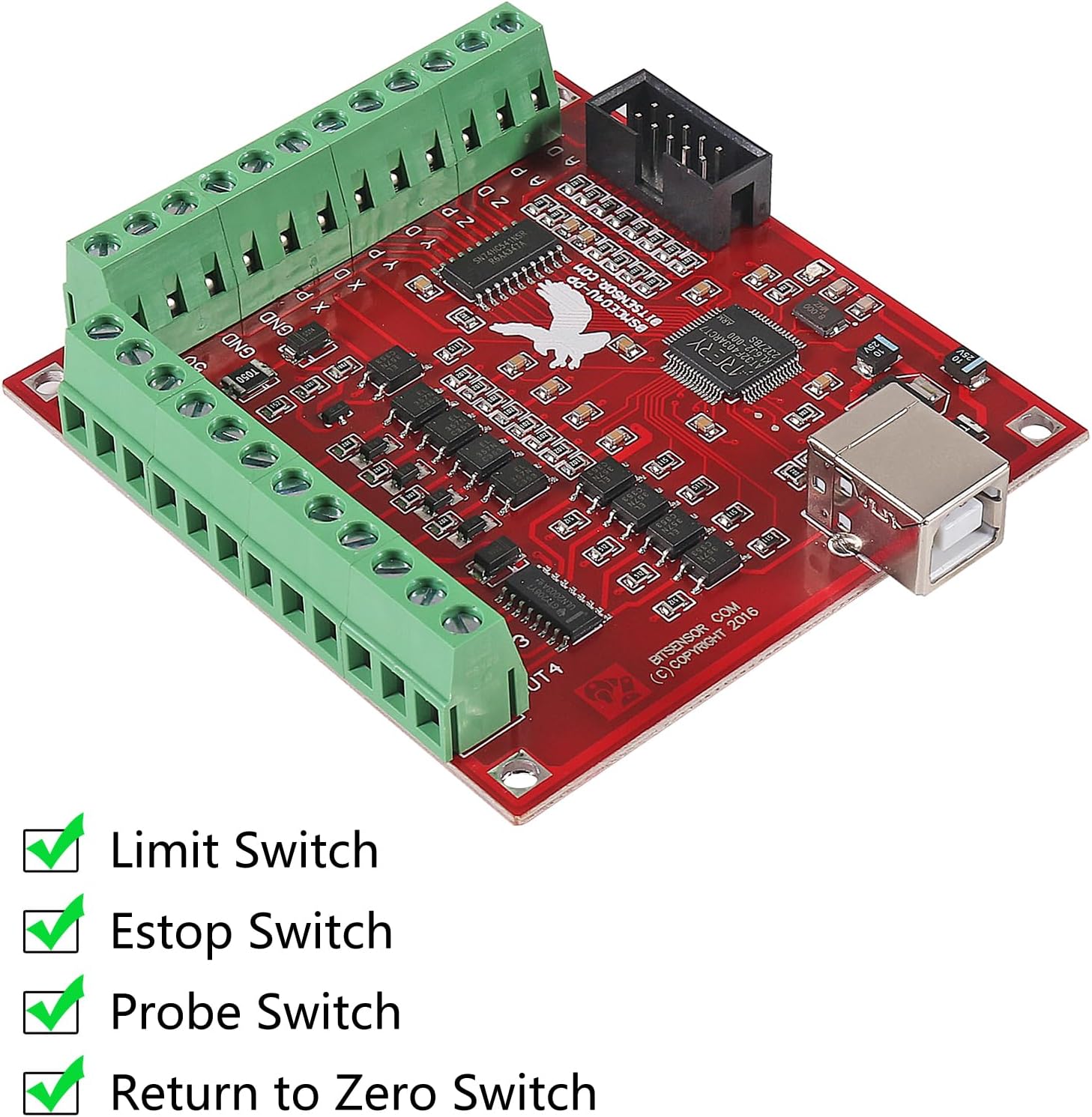
Image 4.2: Supported input switches for the controller board.
- Limit Switches: Connect to prevent axes from exceeding their physical travel limits.
- E-stop Switch: Connect for immediate emergency shutdown of the system.
- Probe Switch: Used for automatic tool length measurement or workpiece probing.
- Return to Zero Switch (Home Switch): Used to establish a precise home position for each axis.
5. Operating Instructions
This section outlines the basic steps for operating the controller card with MACH3 software.
5.1 Software Installation and Configuration
- Install the MACH3 software on your computer. The necessary drivers and software may be included on the provided CD.
- Follow the MACH3 software's instructions to configure the motion controller. This typically involves selecting the correct plugin for the USB interface board.
- Configure the motor tuning parameters (steps per unit, velocity, acceleration) for each axis according to your motor and machine specifications.
- Set up the input pins for limit switches, E-stop, probe, and home switches within MACH3.
- Configure the output pins for spindle control (0-10V) and general-purpose relays (OUT1-OUT4) as needed.
5.2 Basic Operation
- Power On: Ensure the 24V DC power supply is connected and turned on. Connect the USB cable to your computer.
- Software Launch: Open the MACH3 software. The controller should be recognized.
- Axis Movement: Use the jog controls within MACH3 or an electronic handwheel to test individual axis movement.
- Spindle Control: If configured, test the 0-10V output for spindle speed control.
- G-Code Execution: Load your G-code program into MACH3 and initiate the machining process. Monitor the machine's operation closely.
6. Maintenance
To ensure the longevity and reliable operation of your controller card, observe the following maintenance guidelines:
- Keep Clean: Regularly clean the board with a soft, dry brush or compressed air to remove dust and debris. Avoid using liquids.
- Environmental Control: Operate the board in a clean, dry environment, free from excessive humidity, extreme temperatures, and corrosive substances.
- Connection Integrity: Periodically check all wiring connections to ensure they are secure and free from corrosion or damage.
- Power Supply: Ensure your 24V DC power supply is stable and within the specified voltage range.
7. Troubleshooting
This section provides solutions to common issues you might encounter.
- No Power/LEDs Off:
- Verify the 24V DC power supply is connected correctly and is active.
- Check the USB cable connection to both the board and the computer.
- MACH3 Does Not Detect Board:
- Ensure the correct MACH3 plugin for the USB motion controller is installed and selected.
- Try a different USB port on your computer.
- Reinstall the drivers from the provided CD or manufacturer's website.
- Motors Not Moving:
- Check motor wiring to the drivers and driver wiring to the controller board.
- Verify motor tuning parameters in MACH3 (steps per unit, velocity, acceleration).
- Ensure the E-stop is not active and limit switches are not triggered.
- Spindle Control Issues:
- Confirm the 0-10V output is correctly wired to the inverter.
- Check spindle control settings within MACH3.
- Intermittent Operation/Instability:
- Ensure the 24V DC power supply is stable and provides sufficient current.
- Check for electromagnetic interference (EMI) from other equipment. Ensure proper grounding.
8. Warranty and Support
This product is covered by a standard manufacturer's warranty against defects in materials and workmanship. For specific warranty terms and conditions, please refer to the documentation provided with your purchase or contact ACEIRMC customer support.
For technical assistance, troubleshooting beyond this manual, or warranty claims, please contact the seller or ACEIRMC customer service through their official channels. Please have your product model and purchase information ready when contacting support.


