1. Introduction
This manual provides comprehensive instructions for assembling, operating, and maintaining your MUXWELL DIY Electronic Calculator Kit. This kit is designed to function as both a 6-digit calculator and a resistor color code reader, making it an ideal project for electronics enthusiasts and beginners to gain hands-on experience with electronic components and soldering.
The kit includes all necessary components for assembly, offering a practical learning experience. Its compact size and transparent case make it suitable for various workspaces.

Figure 1.1: Assembled DIY Electronic Calculator Kit.
This image displays the fully assembled MUXWELL DIY Electronic Calculator Kit. It features a clear acrylic casing, revealing the blue circuit board, a 6-digit LED display, and an array of white buttons with colored labels for numbers and operations. A coin cell battery holder is visible at the top left.
2. Package Contents
Before beginning assembly, please verify that all components listed below are present in your kit. If any parts are missing or damaged, please contact customer support.

Figure 2.1: All parts included for assembly.
This image shows all individual components of the DIY Electronic Calculator Kit neatly arranged. Visible parts include the main blue printed circuit board (PCB), numerous yellow button switches, white and transparent keycaps, two 6-digit LED display modules, an integrated circuit (IC) chip, a coin cell battery, a battery holder, a USB connector, and the clear acrylic casing pieces along with screws.
Component List:
| Item | Description | Quantity | Note |
|---|---|---|---|
| 1 | Capacitor 1uF (105) | 1 | |
| 2 | Key | 17 | KEY1~KEY17 |
| 3 | White key cap | 17 | |
| 4 | Transparent key cap | 17 | |
| 5 | Key label | 1 | Cut this paper into separated squares with scissors before use. |
| 6 | USB connector | 1 | |
| 7 | LED display module | 2 | P4, P5 |
| 8 | CPU Socket 28 pins | 1 | |
| 9 | CPU STC15W408AS | 1 | U1 |
| 10 | Button battery holder | 1 | BT1 |
| 11 | Button battery CR2032 | 1 | Optional |
| 12 | PCB | 1 | |
| 13 | Shells and screws bag | 1 |
3. Assembly Instructions
This kit is designed for soldering practice. Basic soldering tools (soldering iron, solder, desoldering wick/pump, safety glasses) are required and not included. Always ensure proper ventilation and safety precautions when soldering.

Figure 3.1: Detailed assembly steps.
This image illustrates key soldering steps. It shows close-ups of soldering the 28-pin IC socket, the 1uF capacitor, and the LED display modules. It also depicts the process of inserting the STC15W408AS chipset into the IC socket and installing the four spacers with nuts.
- Prepare Key Labels: Carefully cut the key label paper into individual squares using scissors. These will be placed under the transparent keycaps.
- Solder the 28-pin IC Socket: Locate the 28-pin IC socket (Item 8). Align it correctly with the markings on the PCB (U1) and solder all 28 pins securely. Ensure no solder bridges are formed between pins.
- Solder the 1uF Capacitor: Identify the 1uF (104) capacitor (Item 1). Insert its leads into the designated holes (C1) on the PCB and solder them.
- Solder the USB Connector: Locate the USB connector (Item 6). Align it with the P1 markings on the PCB and solder its pins.
- Solder the Button Battery Holder: Place the button battery holder (Item 10) onto the PCB at the BT1 position and solder its connections.
- Solder the LED Display Modules: Insert the two 6-digit LED display modules (Item 7) into their respective positions (P4, P5) on the PCB. Solder all pins for both modules.
- Solder the Keys: Solder all 17 key switches (Item 2) into their designated positions on the PCB. Ensure they are flush with the board.
- Insert the CPU Chipset: Once all soldering is complete and the board has cooled, carefully insert the STC15W408AS CPU chipset (Item 9) into the 28-pin IC socket. Ensure correct orientation (notch on chip matches notch on socket).
- Assemble Keycaps: Place the cut key labels onto the key switches, then snap the white keycaps (Item 3) over them, followed by the transparent keycaps (Item 4).
- Assemble the Casing: Carefully align the PCB with the bottom acrylic shell. Secure it using the provided screws and spacers. Then, place the top acrylic shell and secure it with the remaining screws.

Figure 3.2: PCB layout with key component locations.
This diagram illustrates the layout of the Printed Circuit Board (PCB), highlighting the locations for the button battery holder (BT1) and the USB connector (P1), which are crucial for power input.

Figure 3.3: Electronic schematic diagram.
This image presents the electronic schematic diagram of the calculator kit, detailing the connections between the CPU (STC15W408AS), LED display modules (3631BS), key matrix, power inputs (CR2032 battery and Micro USB), and other passive components like capacitors.
4. Powering the Device
The calculator kit can be powered by either a CR2032 coin cell battery or via a Micro USB cable. CAUTION: Use either USB or Battery, NOT BOTH simultaneously.
- Coin Cell Battery: Insert the CR2032 battery into the battery holder (BT1) with the positive (+) side facing up. The top window allows for easy installation and removal.
- Micro USB Power: Connect a Micro USB cable to the P1 port on the side of the calculator.
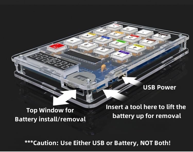
Figure 4.1: Power input options.
This image displays a side view of the assembled calculator, clearly indicating the Micro USB power input port and the top window for installing or removing the CR2032 coin cell battery. A caution note emphasizes using only one power source at a time.
5. Operating Instructions
The MUXWELL DIY Electronic Calculator Kit features dual functionality: a standard 6-digit calculator and a resistor color code reader.

Figure 5.1: Calculator functions and display modes.
This image provides a detailed overview of the calculator's interface, labeling the 6-digit display, ON/OFF/Clear button, and indicating how the display changes between Calculator Mode (displaying '0') and Resistor Reader Mode (displaying 'r'). It also highlights the function of the 'Mode' button for switching between these two modes.

Figure 5.2: Button text under transparent caps.
This close-up image showcases the design of the calculator's buttons. Each button features a clear transparent cap that protects the underlying printed label, ensuring durability and fade-free text for prolonged use.
5.1. Calculator Mode
In Calculator Mode, the display shows a '0' (zero) on the far left digit. This mode functions as a standard 6-digit calculator.
- Power On/Off: Press the ON/C button to turn the calculator on or clear the current calculation.
- Basic Operations: Use the number buttons (0-9) and operation buttons (+, -, ×, ÷) for calculations.
- Decimal Point: Use the '.' button for decimal numbers.
- Equals: Press the '=' button to display the result of a calculation.
5.2. Resistor Reader Mode
In Resistor Reader Mode, the display shows an 'r' (lowercase 'r') on the far left digit. This mode allows you to input resistor color codes and get the corresponding resistance value.
- Switching Modes: Long press the Mode button to switch between Calculator Mode and Resistor Reader Mode.
- Inputting Color Codes: Each number button (0-9) corresponds to a specific resistor color:
- 0: Black
- 1: Brown
- 2: Red
- 3: Orange
- 4: Yellow
- 5: Green
- 6: Blue
- 7: Violet
- 8: Gray
- 9: White
- Enter the color codes sequentially (e.g., for a 4-band resistor, enter the first band, second band, third band, and multiplier). The calculator will display the resistance value.
6. Maintenance
To ensure the longevity and proper functioning of your DIY Electronic Calculator Kit, follow these maintenance guidelines:
- Cleaning: Use a soft, dry cloth to clean the transparent casing and buttons. For stubborn smudges, a slightly damp cloth with mild soap can be used, but ensure no liquid enters the internal components. Avoid abrasive cleaners or solvents.
- Storage: Store the calculator in a cool, dry place away from direct sunlight and extreme temperatures.
- Battery Replacement: If using battery power, replace the CR2032 coin cell when the display becomes dim or the calculator stops responding.
- Component Integrity: Periodically inspect the soldered joints for any signs of cracking or corrosion. Re-solder if necessary.
7. Troubleshooting
If you encounter issues with your calculator kit, refer to the following common problems and solutions:
| Problem | Possible Cause | Solution |
|---|---|---|
| Calculator does not power on. | No power source, dead battery, loose power connection. | Ensure battery is correctly inserted or USB cable is connected. Replace battery if needed. Check soldered connections for battery holder/USB port. |
| Display is dim or erratic. | Low battery, poor LED module connection. | Replace battery. Check soldered connections for LED display modules. |
| Buttons are unresponsive. | Loose key switch, incorrect keycap assembly, CPU not seated correctly. | Check soldered connections for the unresponsive key switches. Ensure keycaps are properly seated. Verify the CPU chip is fully inserted into its socket. |
| Incorrect calculations or resistor readings. | Faulty CPU, incorrect component placement, solder bridge. | Double-check all component placements against the schematic. Inspect PCB for any solder bridges or cold joints, especially around the CPU socket and key matrix. |
| Cracked casing or missing screws. | Physical damage during assembly or handling. | Handle with care. Contact customer support for replacement parts if available. |
8. Specifications
- Product Dimensions: 5 x 3.5 x 0.75 inches (127 x 89 x 19 mm)
- Item Weight: 5.6 ounces (158.7 grams)
- Model Number: Hu-054AM
- Brand: MUXWELL
- Calculator Type: Engineering/Scientific (DIY Kit)
- Power Source: Battery Powered (CR2032) or Micro USB
- Material: Plastic (Acrylic Casing)
- Display: 6-Digit LED Display
- Functions: Basic Calculator, Resistor Color Code Reader

Figure 8.1: Product dimensions and weight.
This image provides a visual representation of the assembled calculator's dimensions, indicating a width of 90mm, a height of 128mm, and a thickness of 15.5mm. It also states the weight with the case as 151g and without the case as 77g.
9. Safety Information
Please observe the following safety precautions:
- This product is for external use only.
- Always wear appropriate personal protective equipment (PPE), such as safety glasses, when soldering.
- Ensure adequate ventilation in your workspace to avoid inhaling solder fumes.
- Keep soldering irons and hot components away from flammable materials.
- Do not use both USB power and battery power simultaneously.
- Keep small components and batteries out of reach of children to prevent accidental ingestion.
10. Warranty and Support
MUXWELL is committed to providing quality products. For any questions, technical assistance, or support regarding your DIY Electronic Calculator Kit, please refer to the seller's contact information on the platform where the product was purchased.
Please note that this is a DIY kit, and successful assembly depends on the user's soldering skills and adherence to instructions. Damage resulting from improper assembly or misuse may not be covered under standard return policies.


