1. Introduction
This manual provides detailed instructions for the installation, operation, and maintenance of the Aoleaby XR64CX-5N1C3 Temperature Controller. This device is designed for precise temperature management, offering features such as fast response, high stability, and data recording capabilities. Please read this manual thoroughly before using the product to ensure correct operation and to prevent damage.
2. Safety Information
- Electrical Safety: Ensure all electrical connections are made by a qualified professional and comply with local electrical codes. Disconnect power before installation or maintenance.
- Environmental Conditions: Do not expose the controller to excessive moisture, dust, or extreme temperatures outside its specified operating range.
- Proper Use: Use the controller only for its intended purpose as a temperature management device. Any unauthorized modifications or misuse may result in damage or injury.
- Handling: Handle the device with care to avoid physical damage.
3. Product Overview
The Aoleaby XR64CX-5N1C3 is a compact and user-friendly temperature controller. It features a digital display for temperature readings and several buttons for configuration and control.
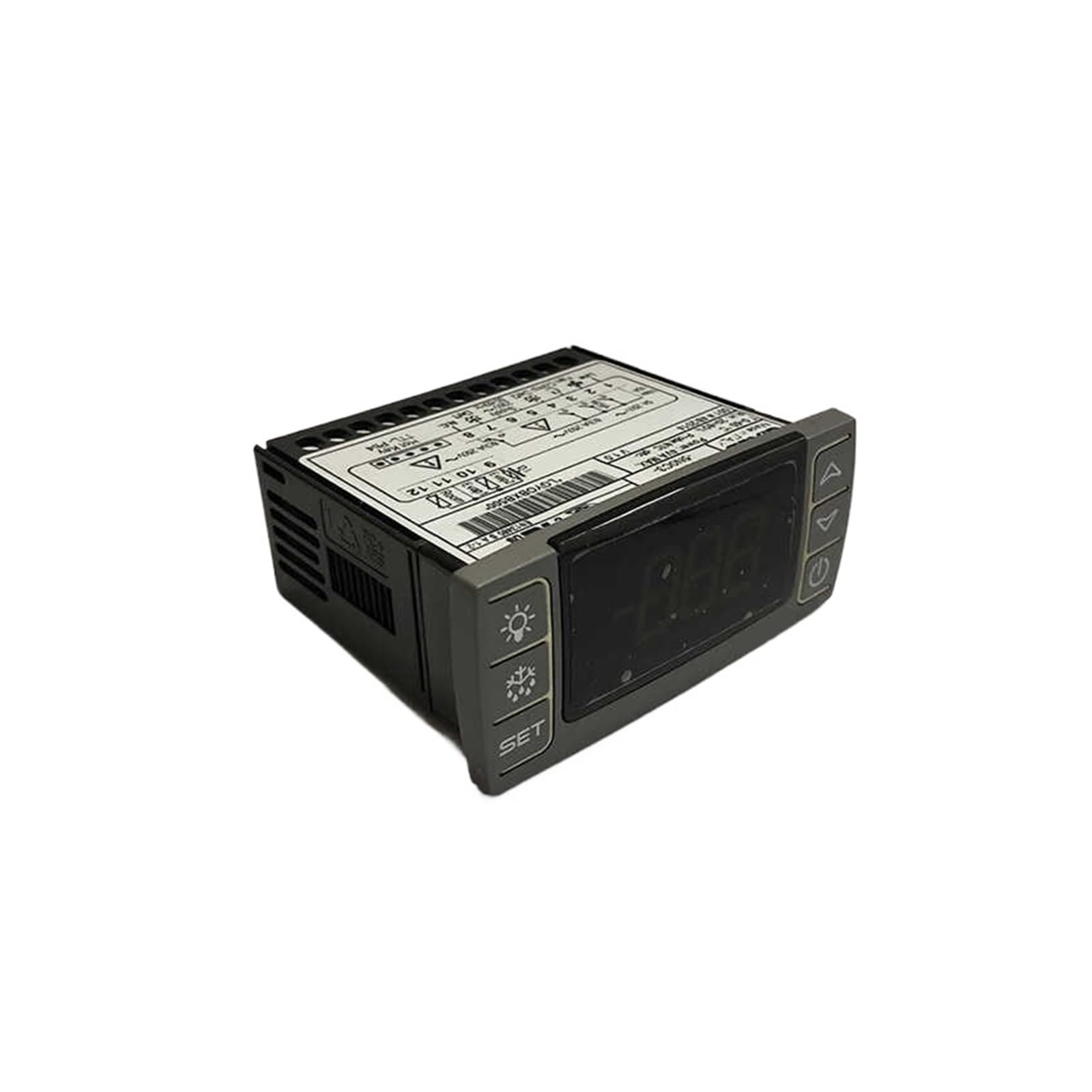
Figure 1: Front view of the Aoleaby XR64CX-5N1C3 Temperature Controller. The display shows temperature readings, and buttons on the left and right allow for setting parameters and controlling functions like defrost and light.
3.1. Control Panel Layout
- Digital Display: Shows current temperature and parameter values.
- SET Button: Used to enter parameter setting mode or confirm selections.
- Light Button (Bulb icon): Controls the internal light (if applicable) or other auxiliary functions.
- Defrost Button (Snowflake/Water drop icon): Initiates or controls the defrost cycle.
- Up Arrow Button: Increases values or navigates through menu options.
- Down Arrow Button: Decreases values or navigates through menu options.
- Power Button (Circle with vertical line): Turns the device on/off or enters standby mode.
4. Setup and Installation
Proper installation is crucial for the optimal performance and longevity of the temperature controller. Ensure power is disconnected before proceeding.
4.1. Mounting
The controller is designed for panel mounting. Cut an appropriate opening in the panel according to the dimensions provided in the specifications. Insert the controller and secure it using the provided clips or mounting hardware.
4.2. Electrical Connections
Refer to the wiring diagram typically found on the side or back of the unit, or in a separate wiring guide. Connect the power supply, temperature sensors, and output loads (e.g., compressor, fan, heater) to the corresponding terminals. Ensure all connections are secure and correctly polarized.
- Power Supply: Connect to the specified voltage and frequency.
- Sensor Inputs: Connect temperature probes to the designated sensor terminals.
- Relay Outputs: Connect the controlled devices (e.g., refrigeration unit, defrost heater) to the appropriate relay outputs.
Note: Incorrect wiring can damage the unit and connected equipment. If unsure, consult a qualified electrician.
5. Operating Instructions
The XR64CX-5N1C3 controller is designed for ease of use, offering intuitive control over temperature settings and functions.
5.1. Powering On/Off
Press and hold the Power Button (Circle with vertical line icon) for a few seconds to turn the controller on or off.
5.2. Viewing Current Temperature
Upon powering on, the digital display will show the current temperature measured by the primary sensor.
5.3. Setting the Setpoint Temperature
- Press the SET Button once. The display will show the current setpoint value.
- Use the Up Arrow or Down Arrow buttons to adjust the setpoint to the desired temperature.
- Press the SET Button again to confirm and save the new setpoint. If no button is pressed for several seconds, the controller will automatically exit the setting mode without saving changes.
5.4. Accessing and Modifying Parameters
Advanced parameters control various aspects of the controller's operation, such as differential, defrost cycles, and sensor calibration.
- Press and hold the SET Button for approximately 3 seconds to enter the parameter setting menu. The display will show the first parameter code.
- Use the Up Arrow or Down Arrow buttons to scroll through the parameter codes.
- Once the desired parameter code is displayed, press the SET Button to view its current value.
- Use the Up Arrow or Down Arrow buttons to modify the parameter value.
- Press the SET Button to confirm and save the new value.
- To exit the parameter setting menu, press the Power Button or wait for the timeout.
5.5. Manual Defrost
To initiate a manual defrost cycle, press and hold the Defrost Button (Snowflake/Water drop icon) for a few seconds. The defrost indicator will illuminate, and the cycle will begin according to programmed parameters.
5.6. Light Control
Press the Light Button (Bulb icon) to toggle the internal light or other auxiliary functions connected to this output.
5.7. Data Recording and Analysis
The controller supports data recording of temperature values. For data export and analysis, refer to the specific instructions for connecting the controller to a compatible data logging system or software, if available for this model. This feature allows for monitoring temperature trends and ensuring optimal performance over time.
6. Maintenance
Regular maintenance ensures the longevity and accurate operation of your temperature controller.
6.1. Cleaning
- Disconnect power before cleaning.
- Wipe the display and control panel with a soft, damp cloth. Do not use abrasive cleaners, solvents, or excessive moisture, as these can damage the unit.
- Ensure no liquid enters the controller's casing.
6.2. Sensor Inspection
Periodically inspect the temperature sensors for any signs of damage or corrosion. Ensure they are securely placed in their intended measurement locations and are free from obstructions that could affect accuracy.
6.3. Electrical Connections
Occasionally check all electrical connections for tightness and signs of wear or overheating. Loose connections can lead to intermittent operation or electrical hazards.
7. Troubleshooting
This section addresses common issues you might encounter with the XR64CX-5N1C3 temperature controller.
| Problem | Possible Cause | Solution |
|---|---|---|
| Controller does not power on. | No power supply; incorrect wiring; faulty unit. | Check power connections and supply voltage. Verify wiring against the diagram. If issues persist, contact support. |
| Display shows "Err" or abnormal readings. | Sensor fault; sensor disconnected; sensor out of range. | Check sensor connections. Inspect sensor for damage. Replace sensor if necessary. |
| Temperature control is inaccurate. | Sensor placement; incorrect parameter settings; sensor calibration issue. | Ensure sensor is correctly placed and not affected by external heat sources. Verify setpoint and differential parameters. Check sensor calibration. |
| Output (e.g., compressor) does not turn on/off. | Incorrect wiring; faulty relay; parameter settings (e.g., delay times). | Verify output wiring. Check relevant parameters like compressor delay or differential. Test the connected device independently. |
If you encounter problems not listed here or if the suggested solutions do not resolve the issue, please contact customer support.
8. Specifications
Below are the technical specifications for the Aoleaby XR64CX-5N1C3 Temperature Controller.
- Model: XR64CX-5N1C3
- Brand: Aoleaby
- Package Dimensions: 1.18 x 0.79 x 0.39 inches
- Item Weight: 1.32 pounds (600 Grams)
- Color: One Color
- Manufacturer: Aoleaby
- Assembly Required: No
- Number of Pieces: 1
9. Customer Support
For technical assistance, warranty information, or service inquiries, please contact your retailer or the manufacturer directly. Please have your product model number (XR64CX-5N1C3) available when contacting support.
