
1. Introduction
This manual provides detailed instructions for the proper setup, operation, and maintenance of your Radiolink AT10II 12-Channel 2.4G RC Transmitter. Please read this manual thoroughly before using the product to ensure safe and efficient operation. The AT10II is designed for a variety of RC models including airplanes, FPV racing drones, quadcopters, helicopters, cars, and boats.

Figure 1: Radiolink AT10II 12-Channel RC Transmitter.
2. Key Features
- Advanced Anti-Interference: Utilizes DSSS and FHSS communication technology with a 7dBi high-gain antenna for stable signal transmission and a control range of up to 2.5 miles (4 km) in open air.
- Real-time Telemetry: Monitors aircraft voltage on the AT10II screen when combined with the PRM-01 module (included). With the PRM-03 module (sold separately) and compatible flight controllers (Crossflight, APM, Pixhawk, Mini Pix), it provides telemetry data such as battery voltage, speed, altitude, RSSI, and distance.
- Comprehensive Functionality: Features 20mW power, 12 channels, battery voltage telemetry, RSSI telemetry, dual/triple rates, throttle lock, failsafe configuration, End Point Adjustment (EPA), customizable switches, and channel mix control.
- Wide Receiver Compatibility: Compatible with Radiolink R12DS, R12DSM, R9DS, R6DS, and R6DSM receivers.
- Model Memory: Stores up to 15 models, allowing quick switching between helicopter, quadcopter, fixed-wing, glider, car, BoxBot, and boat configurations.
- User-Friendly Interface: Supports both basic and advanced menus for diverse user needs, with an intuitive and easy-to-navigate user interface. No complex radio configuration is required for binding.
- Safety Alerts: Includes RSSI indicator alerts, low voltage alarms, and failsafe protection. Audible and visual (DD alarm words on the 3.5" LCD) reminders are provided for critical conditions.
- Customizable Controls: Equipped with 3 VR switches, 3 three-way switches, 4 two-way switches, and 1 trainer reset switch. All 12 channels can be assigned to any switch.
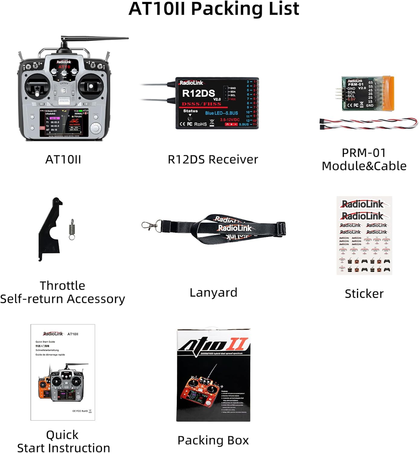
Figure 2: Overview of Radiolink AT10II key features.
3. Product Overview
3.1. Transmitter Components
The Radiolink AT10II transmitter features an ergonomic design with multiple switches and controls for precise operation. The main components include:
- Joysticks: Two primary control sticks for pitch, roll, yaw, and throttle.
- Switches: Various 2-way, 3-way, and VR (variable resistor) switches for assigning auxiliary functions.
- LCD Screen: A 3.5-inch LCD for displaying telemetry data, menu navigation, and system settings.
- Navigation Dial/Buttons: For menu navigation and parameter adjustments.
- Antenna: Integrated 7dBi high-gain antenna.
- USB Port: For firmware updates (not for charging).

Figure 3: Ergonomic appearance and multiple switches of the AT10II.
3.2. Packing List
The standard package includes the following items:
- AT10II Transmitter
- R12DS Receiver
- PRM-01 Module & Cable
- Throttle Self-return Accessory
- Lanyard
- Sticker
- Quick Start Instruction
- Packing Box

Figure 4: Contents of the Radiolink AT10II package.
4. Setup and Binding
4.1. Connecting the Receiver and Telemetry Module
To enable telemetry functions, connect the PRM-01 module to your receiver and the aircraft's battery. The R12DS receiver supports both PWM (11 channels) and SBUS (12 channels) signal output modes.

Figure 5: R12DS receiver showing PWM and SBUS signal output modes.
Video: Telemetry Airplane's Battery Voltage on AT9S Pro's Screen
This video demonstrates how to connect the PRM-01 telemetry module to the R9DS receiver and an airplane's battery to display real-time voltage on the AT9S Pro transmitter screen.
4.2. Channel Configuration for Receivers
When using different receivers (e.g., 10-channel vs. 12-channel), it is crucial to adjust the transmitter's channel setting to match the receiver. Failure to do so may result in unstable servo operation or loss of control.
Video: How to make the 10CH AT9S Pro work with 12CH receiver?
This video illustrates the process of changing the channel selection on the AT9S Pro transmitter to ensure proper functionality with both 10-channel and 12-channel receivers.
5. Operating Instructions
5.1. Throttle Configuration
The AT10II supports changing the throttle stick from left to right, or setting it to dual-stick back to center. This allows users to configure the transmitter according to their preferred mode (Mode 1 or Mode 2).

Figure 6: Throttle configuration options: Left Throttle (Mode 2), Dual-stick Back to Center, and Right Throttle (Mode 1).
5.2. Throttle Cut Function
Setting up a Throttle Cut function is crucial for safety, preventing accidental motor activation. It also allows for quick modification of the maximum throttle output.
Video: How to set the Throttle Cut function on T8FB?
This video demonstrates the steps to set up the Throttle Cut function on a Radiolink T8FB transmitter, a similar process applicable to the AT10II for safety and control.
5.3. Programmable Mix Control
The AT10II offers 8 groups of programmable mix control, allowing advanced users to customize control responses for complex maneuvers or specific model types.

Figure 7: Screen displaying programmable mix control settings.
5.4. Usage Recommendations
The AT10II is versatile and suitable for various RC applications. Examples include:
- RC Cars: Utilize knob switches for camera angle adjustments and other auxiliary functions.
- RC Trucks: Control truck lights (ON/OFF) and sounds using dedicated switches.
- RC Airplanes: Use 2-way switches for throttle cut or landing gear control.
- RC Drones/Quadcopter: Employ 2/3-way switches for flight attitude changes.

Figure 8: Guide to switches and their typical usage in various RC models.
6. Maintenance
To ensure the longevity and optimal performance of your Radiolink AT10II transmitter, follow these maintenance guidelines:
- Cleaning: Use a soft, dry cloth to clean the transmitter. Avoid using solvents or abrasive cleaners.
- Storage: Store the transmitter in a cool, dry place away from direct sunlight and extreme temperatures. Remove batteries if storing for extended periods.
- Firmware Updates: Regularly check the official Radiolink website for firmware updates to ensure your transmitter has the latest features and bug fixes. Updates are performed via the USB port.
- Battery Care: Use recommended battery types (AA*8 or 2S-4S LiPo). Follow proper charging and discharging procedures for LiPo batteries.

Figure 9: Battery compartment for AA or LiPo batteries.
7. Troubleshooting
This section addresses common issues you might encounter with your AT10II transmitter.
7.1. Common Issues and Solutions
| Problem | Possible Cause | Solution |
|---|---|---|
| No signal/Loss of control | Incorrect binding, out of range, receiver/transmitter issue. | Re-bind transmitter and receiver. Check range. Ensure antenna is properly positioned. |
| Servos unstable/unresponsive | Incorrect channel setting on transmitter, faulty servo/receiver. | Verify transmitter channel setting matches receiver (e.g., 10CH for R9DS, 12CH for R12DS). Test with different servos/receivers. |
| Telemetry data not displayed | PRM-01 module not connected correctly, incompatible receiver/flight controller. | Ensure PRM-01 is securely connected to the receiver's telemetry port and battery. Confirm compatibility with your setup. |
| Low voltage alarm | Transmitter or aircraft battery low. | Recharge or replace batteries. Check battery connections. |
7.2. Alarm Sounds and Words
The AT10II provides audible and visual alarms on its LCD screen for various conditions, such as RSSI (Received Signal Strength Indicator) alerts and low voltage warnings. Pay attention to these indicators for safe operation.

Figure 10: Example of an RSSI alarm displayed on the AT10II screen.
8. Specifications
| Feature | Detail |
|---|---|
| Brand | Radiolink |
| Model Number | AT10II |
| Channels | 12 Channels |
| Frequency | 2.4 GHz (DSSS & FHSS) |
| Control Range | Up to 2.5 miles (4 km) in air |
| Power Output | 20 mW |
| Telemetry Support | Voltage (with PRM-01), RSSI, Speed, Altitude, Distance (with PRM-03 & compatible FC) |
| Compatible Receivers | R12DS, R12DSM, R9DS, R6DS, R6DSM |
| Model Memory | 15 models |
| Display | 3.5 inch LCD |
| Power Source | 8 x AA batteries or 2S-4S LiPo battery |
| Material | Plastic |
| Dimensions | 18 x 9.4 x 22.1 cm |
| Color | Grey |
9. Support
For further assistance, technical support, or warranty inquiries, please contact the Radiolink after-sales team. You can typically find support information through the official Radiolink store on Amazon or via their online user instructions.
For the latest information and resources, please visit the official Radiolink website: www.radiolink.com


