
1. Introduction
This manual provides essential information for the safe and effective use of the EQBVZZRD TBT7-R1-200-240VAC Asymmetric Cycle Time Relay. This electronic repeat relay is designed for various time-controlled applications in industrial equipment, lighting, and manufacturing. It offers a wide range of functions and a broad voltage compatibility.
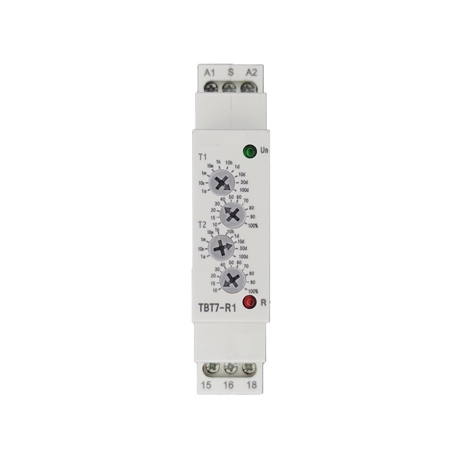
Figure 1: Front view of the TBT7-R1-200-240VAC Time Relay.
2. Safety Information
Please read and understand all safety instructions before installation and operation. Failure to follow these instructions may result in electric shock, fire, or serious injury.
- Ensure power is disconnected before performing any wiring or maintenance.
- Installation should be performed by qualified personnel only.
- Verify correct voltage and current ratings before connecting the device.
- Do not expose the device to moisture or extreme temperatures.
- Use appropriate personal protective equipment (PPE) during installation.
3. Product Features
The EQBVZZRD TBT7-R1-200-240VAC Time Relay offers the following key features:
- Multifunctional Operation: Features up to 10 function choices including delay on, delay off, interval, cycle, single shot, latching, and pulse.
- Robust Construction: Made with a flame-retardant shell, ensuring durability and reliable performance even in challenging environments.
- Easy Installation: Includes a wiring diagram printed on the product shell for straightforward connection. Utilizes tunnel-type terminals for secure and stable wiring.
- Wide Application Range: Suitable for industrial equipment, lighting systems, manufacturing processes, and other time-controlled applications.
- Compact Design: Small in size and light in weight, facilitating easy integration into various setups.
4. Specifications
| Specification | Value |
|---|---|
| Model | TBT7-R1-200-240VAC |
| Brand | EQBVZZRD |
| Input Voltage | 12V-240VAC/DC (Universal) |
| Time Range | 0.1 seconds - 100 days |
| Output Contact | 16A / 250V~ (AC1) |
| Item Weight | 400 Grams |
5. Setup and Installation
The TBT7-R1-200-240VAC Time Relay is designed for DIN rail mounting. Follow the steps below for proper installation and wiring.
5.1 Mounting
Mount the relay onto a standard 35mm DIN rail in an appropriate enclosure, ensuring adequate ventilation and protection from environmental factors.
5.2 Wiring
Refer to the wiring diagram printed on the side of the relay for connection details. Ensure all connections are secure using the tunnel-type terminals.

Figure 2: Wiring diagram for the TBT7-R1 Time Relay. Terminals Un, S, R, A1, A2, 15, 16, 18 are shown with their respective connections for power input, control input, and output contacts.
Key Terminals:
- Un: Power supply input (12V-240VAC/DC).
- S: Control input for triggering functions.
- A1, A2: Auxiliary power terminals (if applicable, refer to specific function mode).
- 15: Common contact for the output relay.
- 16: Normally Closed (NC) contact.
- 18: Normally Open (NO) contact.
Always double-check all connections before applying power.
6. Operating Instructions
The TBT7-R1-200-240VAC Time Relay features adjustable dials for setting time ranges (T1 and T2) and percentage adjustments for fine-tuning. The specific function mode is typically selected via a rotary switch or dip switches on the device, which is not detailed in the provided information. Refer to the markings on your specific unit for function selection.

Figure 3: Front panel showing T1 and T2 time setting dials. Each dial has a range selector (1s, 10s, 1m, 10m, 1h, 10h, 1d, 10d, 100d) and a percentage adjustment dial (0-100%).
6.1 Setting Time Ranges (T1 and T2)
The relay features two independent time settings, T1 and T2, which are used for various asymmetric cycle functions. Each setting consists of two dials:
- Range Selector Dial: This dial allows you to select the base time unit (e.g., 1 second, 1 minute, 1 hour, 1 day) and its multiplier (e.g., 1, 10, 100). Available ranges typically include 0.1s-1s, 1s-10s, 10s-1m, 1m-10m, 10m-1h, 1h-10h, 10h-1d, 1d-10d, 10d-100d.
- Percentage Adjustment Dial: Once a range is selected, this dial allows for fine adjustment within that range, typically from 0% to 100%. For example, if the range is set to 1s-10s, setting the percentage dial to 50% would result in a 5-second delay.
Adjust T1 and T2 according to the desired timing sequence for your chosen function mode.
6.2 Function Selection
The relay supports up to 10 different operating functions. The method for selecting these functions (e.g., rotary switch, dip switches, or external wiring configuration) is not explicitly detailed in the provided product information. Please consult the specific markings on your device or the manufacturer's supplementary documentation for detailed instructions on function mode selection.
7. Maintenance
The EQBVZZRD TBT7-R1-200-240VAC Time Relay is designed for minimal maintenance. Follow these general guidelines:
- Keep the device clean and free from dust and debris. Use a soft, dry cloth for cleaning.
- Periodically inspect wiring connections to ensure they remain tight and secure.
- Ensure the operating environment remains within the specified temperature and humidity ranges.
- Do not attempt to open or repair the device yourself. Refer to qualified service personnel for any repairs.
8. Troubleshooting
If the time relay is not functioning as expected, consider the following:
- No Power: Check the power supply connections (Un terminals) and ensure the voltage is within the 12V-240VAC/DC range. Verify circuit breakers or fuses.
- Incorrect Timing: Re-check the T1 and T2 dial settings, including both the range selector and the percentage adjustment. Ensure the selected function mode is appropriate for the desired operation.
- Output Not Switching: Verify the load connections to terminals 15, 16, and 18. Ensure the load is within the relay's contact rating (16A / 250V~). Check if the control input (S terminal) is being triggered correctly.
- Intermittent Operation: Inspect all wiring for loose connections or damaged insulation. Ensure the operating environment is stable and free from excessive electrical noise or vibration.
If issues persist after checking these points, contact the manufacturer or a qualified technician for assistance.
9. Warranty and Support
For warranty information and technical support, please refer to the documentation provided with your purchase or contact the seller directly. Specific warranty terms and conditions may vary.