1. Introduction
This manual provides essential information for the safe and efficient installation, operation, and maintenance of your FPBIGCHA 800W CNC Spindle Motor Kit. This kit includes an 800W water-cooled spindle, a 1.5kW Variable Frequency Drive (VFD), a water pump, a 65mm bracket, and ER11 collets. Please read this manual thoroughly before using the product to ensure proper function and to prevent damage or injury.
2. Safety Information
Always prioritize safety when working with electrical and mechanical equipment. Failure to follow these safety guidelines may result in serious injury, electric shock, or damage to the equipment.
- Electrical Safety: Ensure all electrical connections are made by a qualified professional. Verify that the input voltage (220V) matches your power supply. Always disconnect power before performing any maintenance or wiring changes. Ensure proper grounding for all components, especially the VFD and spindle.
- Mechanical Safety: The spindle operates at high speeds (up to 24000 RPM). Keep hands, loose clothing, and long hair away from rotating parts. Always wear appropriate Personal Protective Equipment (PPE), including safety glasses, hearing protection, and gloves.
- Water Cooling: Ensure the water cooling system is properly filled and circulating before operating the spindle. Check for leaks regularly. Use clean, distilled water or a recommended coolant to prevent corrosion and blockages.
- Environment: Operate the equipment in a clean, dry, and well-ventilated area. Avoid operating in dusty or humid environments.
- Emergency Stop: Familiarize yourself with the emergency stop procedures for your CNC machine and VFD.
3. Package Contents
The FPBIGCHA 800W CNC Spindle Motor Kit typically includes the following components. Please verify all items are present upon unboxing.

Image 3.1: Overview of the 800W 220V Water Cooled Cylindrical Spindle Kit components. This image displays the 1.5kW VFD, 800W water-cooled spindle, 65mm spindle clamp/bracket, ER11 collets, ER11A wrench, 75W water pump, and 5-meter water pipe, along with their respective net weights.
- 1.5kW HS320 Frequency Changer (VFD): For controlling spindle speed and power. Net weight: 826g.
- 800W 220V ER11 Water Cooled Cylindrical Spindle: The main cutting tool motor. Net weight: 2.85kg.
- 65mm Spindle Clamp/Bracket (with 4 holes): For securely mounting the spindle. Net weight: 550g.
- ER11 Collet Set (9 pieces, 1-7mm): For holding various tool shank sizes. Net weight: 60g.
- ER11A Wrench: For tightening and loosening ER11 collets. Net weight: 78g.
- 75W Water Pump: For circulating coolant through the spindle. Net weight: 900g.
- 5m Water Pipe: For connecting the water pump to the spindle. Net weight: 180g.
4. Specifications
Detailed specifications for the main components of the kit are provided below.
4.1. 800W Water Cooled Spindle (Model: HTZ65-0.8-ER11)

Image 4.1: Detailed dimensions and specifications for the HTZ65-0.8-ER11 water-cooled spindle.
| Parameter | Value | Parameter | Value |
|---|---|---|---|
| Model Number | HTZ65-0.8-ER11 | Current (A) | 3.5 |
| Rotational Speed (RPM) | 24000 | Frequency (Hz) | 400 |
| Power (KW) | 0.8 | Dimension | Ø65x198mm |
| Voltage (V) | 220 | Weight (KG) | 2.85 |
| Cooling Method | Water Cooling | Bearings | 4 pcs 7002 |
| Collet Type | ER11 | Max Torque | 0.32Nm |
4.2. 1.5kW VFD (Model: HS320-1.5S1-220V)
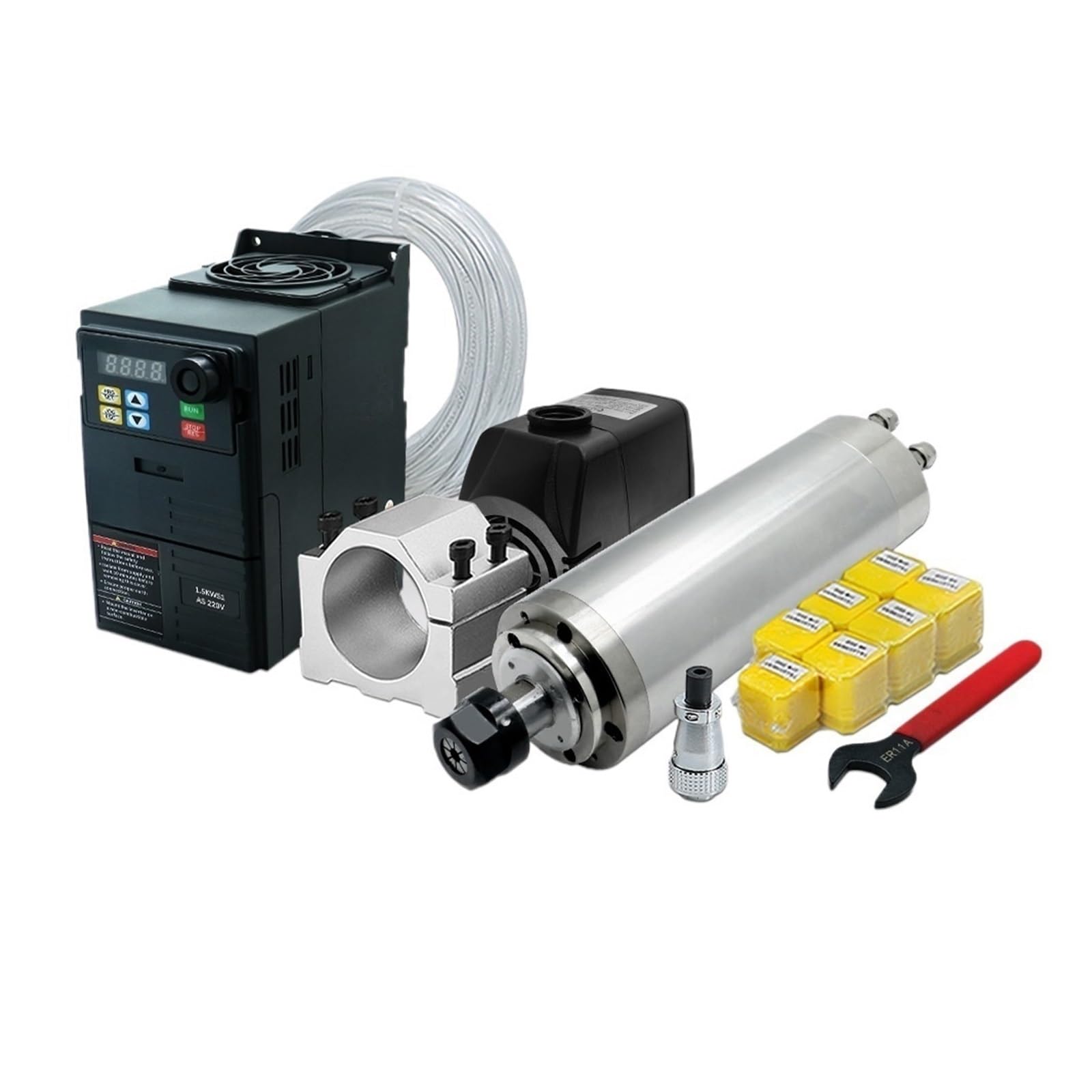
Image 4.2: Dimensions and product parameters for the HS320 1.5kW inverter.
| Parameter | Value | Parameter | Value |
|---|---|---|---|
| Product Model | HS320-1.5S1-220V | Output Current | 7.0 A |
| Frequency | 50/60 Hz | Voltage | 220 V |
| Power | 1.5 KW | Net Weight | 0.8 Kg |
4.3. 75W Water Pump

Image 4.3: Specifications and dimensions for the 75W water pump.
| Parameter | Value |
|---|---|
| Voltage | 220V |
| Power | 75W |
| Head of Lift | 3.2m |
| Flow Rate | 3200L/H |
| Weight | 900g |
5. Setup
5.1. Spindle Mounting
Mount the 800W spindle securely onto your CNC machine using the provided 65mm spindle clamp/bracket. Ensure the bracket is firmly attached to the machine frame and the spindle is tightly clamped within the bracket to prevent vibration and movement during operation.

Image 5.1: Dimensions of the 65mm spindle clamp/bracket, showing fixture points and overall size.
5.2. Water Cooling System Connection
The water cooling system is critical for maintaining the spindle's operating temperature and extending its lifespan.
- Prepare Coolant: Fill a suitable reservoir (not included) with clean, distilled water or a recommended coolant. The reservoir should be large enough to ensure adequate cooling.
- Connect Water Pump: Place the 75W water pump into the coolant reservoir.
- Connect Water Pipe: Attach one end of the 5-meter water pipe to the outlet of the water pump and the other end to the inlet port of the spindle. Connect a return pipe from the spindle's outlet port back to the reservoir. Ensure all connections are secure and leak-free.
- Test System: Before powering the spindle, turn on the water pump to verify proper water circulation and check for any leaks. Ensure water flows freely through the spindle and returns to the reservoir.

Image 5.2: The 75W water pump and 5-meter water pipe, essential components for the spindle's cooling system.
5.3. Electrical Connections (VFD and Spindle)
WARNING: Electrical connections should only be performed by qualified personnel. Ensure power is disconnected before wiring.
- VFD Input Power: Connect your 220V single-phase AC power supply to the input terminals of the HS320 VFD (typically marked L and N, or R and S). Ensure proper grounding (GND) is established.
- VFD to Spindle Wiring: Connect the output terminals of the VFD (U, V, W) to the corresponding pins on the spindle's aviation plug. Refer to the wiring diagram below for correct pin assignments. The spindle typically uses a 4-pin connector.
- Grounding: Ensure the spindle body is properly grounded to the VFD and your CNC machine frame.

Image 5.3: Wiring diagram illustrating the connection between the VFD (Inverter) and the main spindle. Pins 1, 2, 3 on the spindle connector correspond to U, V, W outputs from the VFD, and pin 4 is for ground.
Note: The VFD may require specific parameter settings (e.g., maximum frequency, rated current, acceleration/deceleration times) to match the 800W spindle. Consult the VFD's specific manual for detailed parameter configuration.
6. Operating Instructions
6.1. Pre-Operation Checks
- Verify all electrical connections are secure and correct.
- Ensure the spindle is firmly mounted.
- Confirm the water cooling system is functioning, with adequate coolant and no leaks.
- Check that the ER11 collet and cutting tool are properly installed and tightened.
6.2. ER11 Collet and Tool Installation
The ER11 collet system allows for quick and precise tool changes.
- Assemble Collet and Nut: Insert the ER11 collet into the collet nut. Ensure the collet snaps into the eccentric ring of the nut.
- Insert Tool: Place the shank of your cutting tool into the collet. Ensure the tool is inserted deep enough to provide secure clamping, but not so deep that it bottoms out.
- Attach to Spindle: Screw the assembled collet and nut onto the spindle shaft.
- Tighten: Use the provided ER11A wrench to firmly tighten the collet nut. Do not overtighten, but ensure the tool is securely held.
Image 6.1: ER11 collets and the ER11A wrench used for tool installation and removal. The table shows various ER11 collet sizes.
6.3. VFD Operation and Spindle Start-up
- Power On: Turn on the main power supply to the VFD. The VFD display should illuminate.
- Start Water Pump: Ensure the water pump is running and coolant is circulating through the spindle before starting the spindle motor.
- Set Frequency/Speed: Use the VFD's control panel (e.g., potentiometer, up/down buttons) to set the desired operating frequency (which corresponds to spindle RPM). For this 800W spindle, the maximum frequency is 400Hz for 24000 RPM.
- Start Spindle: Press the 'RUN' button on the VFD. The spindle should gradually accelerate to the set speed. Monitor for any unusual noises or vibrations.
- Stop Spindle: Press the 'STOP' button on the VFD. The spindle will decelerate and stop.
Always allow the spindle to reach its full operating speed before engaging with material. Avoid sudden changes in speed or direction unless specifically required by your machining process and supported by your VFD settings.
7. Maintenance
Regular maintenance ensures the longevity and optimal performance of your spindle kit.
- Water Cooling System:
- Change coolant regularly (e.g., every 1-3 months, depending on usage) to prevent algae growth and contamination.
- Inspect water pipes for kinks, blockages, or leaks.
- Clean the water pump filter (if applicable) and impeller to ensure efficient flow.
- Spindle Bearings: The spindle uses high-speed angular contact ball bearings. These are sealed and generally not user-serviceable. Listen for unusual noises, which may indicate bearing wear.
- Cleaning: Keep the spindle, VFD, and surrounding area clean and free of dust, chips, and coolant residue. Use compressed air to gently clean cooling fins on the VFD.
- Electrical Connections: Periodically check all electrical connections for tightness and signs of corrosion or damage.
8. Troubleshooting
This section addresses common issues you might encounter.
- Spindle Not Starting:
- Check VFD power input and output connections.
- Verify VFD error codes (refer to VFD manual for specific codes).
- Ensure the 'RUN' command is active on the VFD.
- Spindle Overheating:
- Check water pump operation and coolant flow.
- Ensure coolant reservoir has sufficient water and is clean.
- Inspect water pipes for blockages or kinks.
- Reduce spindle load or operating time if consistently overheating.
- Unusual Noise or Vibration:
- Check spindle mounting for looseness.
- Ensure the cutting tool and collet are properly installed and tightened.
- Inspect the cutting tool for damage or imbalance.
- If noise persists, it may indicate bearing wear; contact support.
- VFD Displaying Error Codes: Refer to the specific VFD manual (HS320) for a list of error codes and their corresponding troubleshooting steps.
9. Warranty and Support
For warranty information, technical support, or service inquiries, please contact your retailer or the manufacturer directly. Keep your purchase receipt and product model information handy when contacting support.


