1. Introduction
This manual provides detailed instructions for the safe and effective operation of the ANENG SZ308 Digital Multimeter. The SZ308 is a versatile tool designed for measuring AC/DC voltage, DC current, resistance, continuity, diodes, and hFE triodes. It is suitable for various electrical tasks in household, automotive, and industrial settings.
Please read this manual thoroughly before using the device and keep it for future reference.
2. Safety Information
WARNING: Electrical shock hazard. Improper use of this meter can cause damage, shock, injury, or death. Read and understand all safety information before operation.
- Always ensure the meter is in the correct function and range for the measurement.
- Do not exceed the maximum input values for any range.
- Inspect test leads for damage before each use. Do not use if insulation is compromised.
- Never measure voltage on circuits with power exceeding 1000V.
- Exercise extreme caution when working with live circuits.
- Always disconnect power to the circuit and discharge all high-voltage capacitors before measuring resistance, continuity, or diodes.
- Replace the battery when the low battery indicator appears to ensure accurate readings.
- Do not operate the meter in explosive gas, vapor, or dust environments.
3. Package Contents
Verify that all items are present in your package:
- 1 x ANENG SZ308 Digital Multimeter
- 1 x Pair of Test Leads (Red and Black)
- 1 x 9V Battery (included)
- 1 x Electrical Test Kit (4 connection plugs, 2 PVC cables, 2 copper needles, 2 U-shaped inserts, 2 meter pens, 2 alligator clips) - Note: This kit may vary based on specific product bundles.
- 1 x User Manual

Figure 3.1: ANENG SZ308 Digital Multimeter with included test leads, battery, and additional test kit components.
4. Product Overview
The ANENG SZ308 features a compact design with an anti-skid fuselage for comfortable handling and durability.

Figure 4.1: The compact size and anti-skid design of the ANENG SZ308 Digital Multimeter.
4.1 Display and Controls

Figure 4.2: Front view of the ANENG SZ308 Digital Multimeter, highlighting the digital display and rotary switch functions.
- Digital Display: Clear, easy-to-read LCD screen (1999 counts).
- Rotary Switch: Used to select measurement functions (OFF, V~, V=, hFE, 2m/20m/200m/20/200/1000, 200/2000/20k/200k/2M/20M, DCA, COM, VΩmA).
- Input Jacks:
- COM (Common): For the black test lead.
- VΩmA: For the red test lead when measuring voltage, resistance, or current up to 200mA.
- 10A MAX UNFUSED: For the red test lead when measuring current between 200mA and 10A.
5. Setup
5.1 Battery Installation
The ANENG SZ308 requires one 9V battery (included). Follow these steps to install or replace the battery:
- Ensure the multimeter is turned OFF and disconnect all test leads.
- Locate the battery compartment cover on the back of the unit.
- Use a screwdriver to remove the screw securing the battery cover.
- Gently remove the cover.
- Connect the 9V battery to the battery clips, observing correct polarity (+ to + and - to -).
- Place the battery into the compartment.
- Replace the battery cover and secure it with the screw.

Figure 5.1: Correct polarity for 9V battery installation.
6. Operating Instructions
6.1 General Operation
- Connect the black test lead to the "COM" input jack.
- Connect the red test lead to the appropriate input jack for your measurement (e.g., "VΩmA" for voltage/resistance/low current, "10A MAX UNFUSED" for high current).
- Turn the rotary switch to the desired function and range.
- Touch the test probes to the circuit or component under test.
- Read the measurement value on the digital display.
6.2 Measuring AC Voltage (V~)
- Set the rotary switch to the "V~" range. Select an appropriate range (e.g., 200V, 750V) higher than the expected voltage.
- Connect the red test lead to the "VΩmA" jack and the black test lead to the "COM" jack.
- Apply the test probes across the AC voltage source or load.
- Read the AC voltage value on the display.

Figure 6.1: Example of measuring AC voltage with the multimeter.
6.3 Measuring DC Voltage (V=)
- Set the rotary switch to the "V=" range. Select an appropriate range (e.g., 20V, 200V, 1000V) higher than the expected voltage.
- Connect the red test lead to the "VΩmA" jack and the black test lead to the "COM" jack.
- Apply the red test probe to the positive side and the black test probe to the negative side of the DC voltage source.
- Read the DC voltage value on the display.
6.4 Measuring Resistance (Ω)
- Ensure the circuit is de-energized before measuring resistance.
- Set the rotary switch to the "Ω" range. Select an appropriate range (e.g., 200Ω, 2kΩ, 20kΩ, 200kΩ, 2MΩ, 20MΩ).
- Connect the red test lead to the "VΩmA" jack and the black test lead to the "COM" jack.
- Apply the test probes across the component whose resistance you want to measure.
- Read the resistance value on the display.
6.5 Continuity Test
- Ensure the circuit is de-energized before performing a continuity test.
- Set the rotary switch to the continuity/diode symbol (often shared with resistance).
- Connect the red test lead to the "VΩmA" jack and the black test lead to the "COM" jack.
- Touch the test probes to the two points you want to check for continuity.
- If there is continuity (low resistance), the meter will emit an audible beep. The display will show a low resistance value.
6.6 Diode Test
- Ensure the circuit is de-energized before performing a diode test.
- Set the rotary switch to the diode symbol (often shared with continuity).
- Connect the red test lead to the "VΩmA" jack and the black test lead to the "COM" jack.
- Connect the red test probe to the anode and the black test probe to the cathode of the diode. The display will show the forward voltage drop.
- Reverse the probes. The display should show "OL" (Open Loop) for a good diode.
6.7 hFE (Transistor Gain) Test
- Set the rotary switch to the "hFE" position.
- Identify if the transistor is NPN or PNP.
- Insert the transistor leads (Emitter, Base, Collector) into the corresponding holes in the hFE socket on the multimeter, ensuring correct NPN/PNP orientation.
- Read the hFE value on the display.

Figure 6.2: Performing an hFE (transistor gain) test.
6.8 Square Wave Output
The ANENG SZ308 can generate a square wave signal. This function is typically used for testing audio circuits or other applications requiring a basic pulse signal.
- Set the rotary switch to the "Square Wave" symbol.
- Connect the red test lead to the "VΩmA" jack and the black test lead to the "COM" jack.
- The square wave signal will be output through the test leads. You can connect these to an oscilloscope or other input device to observe the waveform.
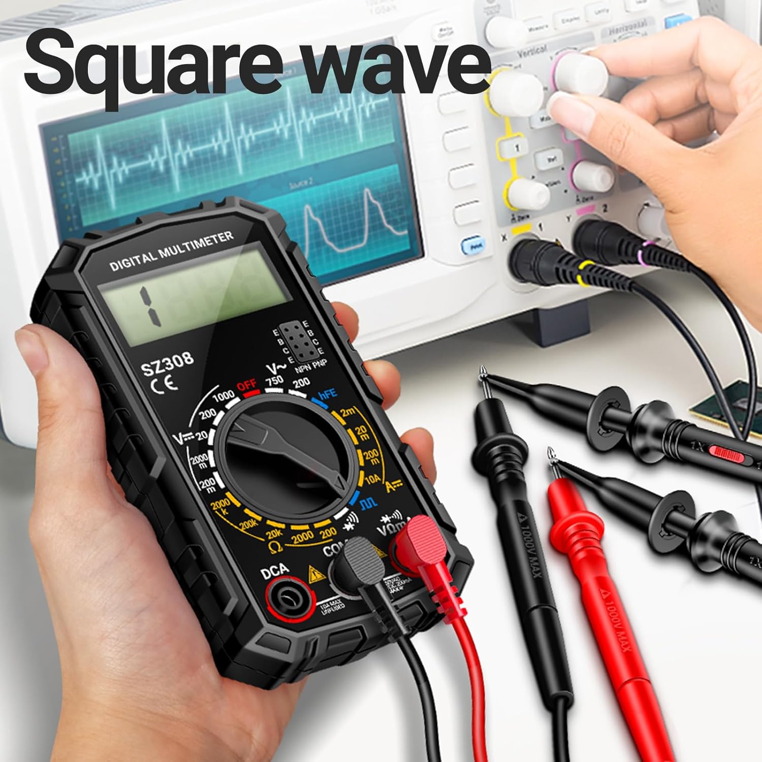
Figure 6.3: Using the square wave output function with an oscilloscope.
7. Maintenance
7.1 Cleaning
Wipe the meter casing with a damp cloth and mild detergent. Do not use abrasives or solvents. Ensure the meter is completely dry before use.
7.2 Battery Replacement
Refer to Section 5.1 for detailed instructions on battery replacement. Always replace the battery when the low battery indicator appears on the display to maintain measurement accuracy.
7.3 Fuse Replacement
The 10A current range is unfused on this model. The VΩmA input jack is typically protected by an internal fuse. If the meter fails to measure current in the mA range, the fuse may need replacement. Fuse replacement should only be performed by qualified personnel. Use only fuses of the specified type and rating.
8. Troubleshooting
- No display or faint display:
- Check battery installation.
- Replace the 9V battery if it is low or depleted.
- "OL" (Overload) displayed:
- The measured value exceeds the selected range. Select a higher range.
- The circuit is open (e.g., during continuity test).
- Incorrect readings:
- Ensure test leads are properly connected.
- Verify the rotary switch is set to the correct function and range.
- Check battery level; low battery can affect accuracy.
- Ensure the circuit is de-energized for resistance, continuity, and diode tests.
- No continuity beep:
- Ensure the meter is in continuity mode.
- Check if the circuit has high resistance.
9. Specifications
| Parameter | Value |
|---|---|
| Model Number | SZ308 |
| Brand | ANENG |
| Display | Digital, 1999 Counts |
| DC Voltage Range | 200mV / 2V / 20V / 200V / 1000V |
| AC Voltage Range | 200V / 750V |
| DC Current Range | 200µA / 2mA / 20mA / 200mA / 10A |
| Resistance Range | 200Ω / 2kΩ / 20kΩ / 200kΩ / 2MΩ / 20MΩ |
| Diode Test | Yes |
| Continuity Buzzer | Yes |
| hFE Test | Yes |
| Square Wave Output | Yes |
| Power Source | 1 x 9V Battery |
| Product Dimensions (L x W x H) | 50 x 50 x 20 mm (approx.) |
| Weight | 0.6 grams (approx.) |
10. Warranty and Support
ANENG provides technical service and support for the SZ308 Digital Multimeter. For any issues or inquiries, please contact ANENG customer service through your purchase channel or the official ANENG website.
Information regarding specific warranty periods and terms may be available on the product packaging or the manufacturer's website.


