
1. Overview
The INA226 is a current shunt and power monitor with an I2C or SMBus compatible interface. This device is designed to simultaneously monitor both shunt voltage drop and bus supply voltage. It incorporates a programmable calibration value, conversion times, and averaging, combined with an internal multiplier, to provide direct readouts of current in amperes and power in watts. The INA226 features up to 16 programmable addresses on its I2C compatible interface, allowing for multiple devices on a single bus.
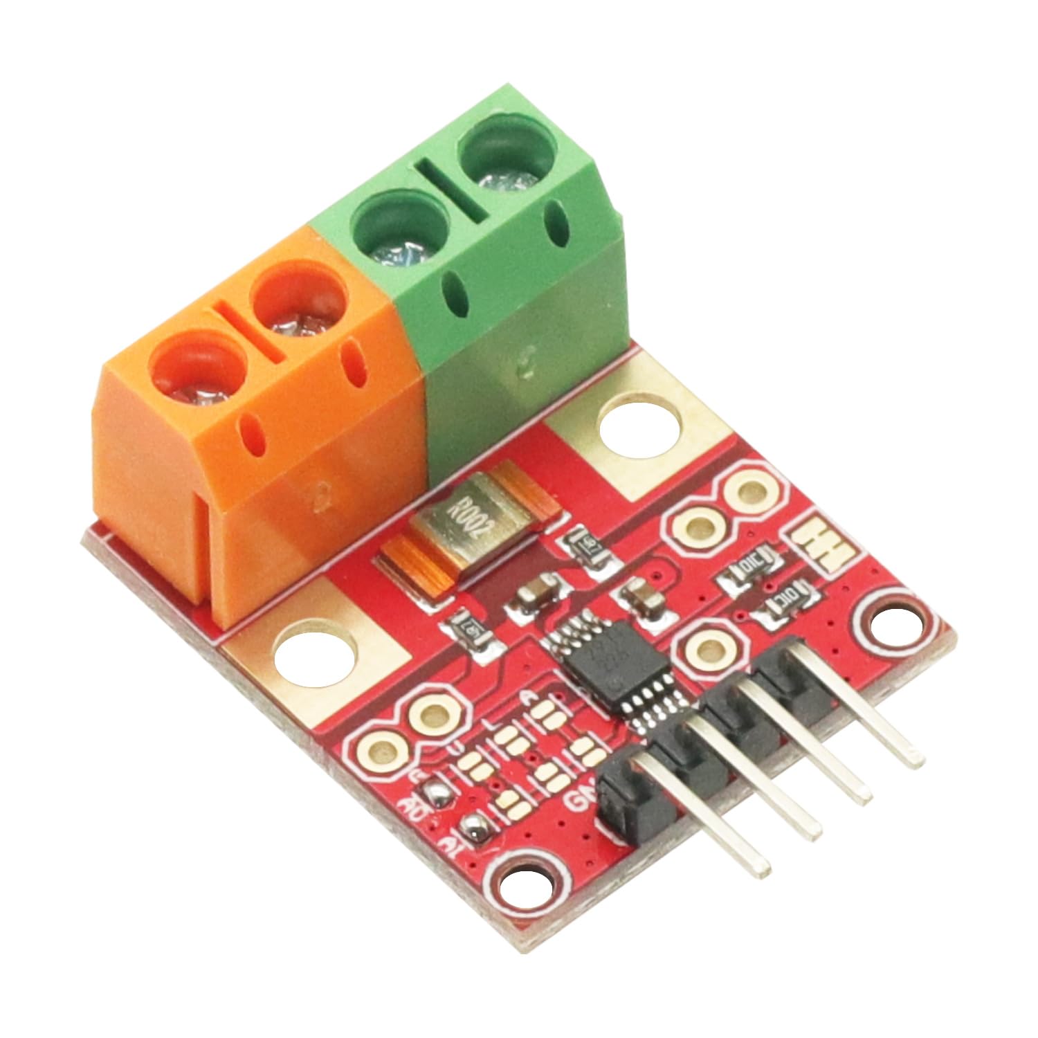
Figure 1: Angled view of the INA226 Voltage Current Monitor module.
2. Key Features
- I2C/SMBus compatible interface for easy integration.
- Simultaneous monitoring of shunt voltage drop and bus supply voltage.
- Direct readout of current in Amperes and power in Watts.
- Programmable calibration value, conversion times, and averaging.
- Configurable IIC address (up to 16 addresses).
- Wide measurement range: 0V to 36V for voltage, -20A to 20A for current.
- High resolution: 16-bit ADC.
- Broad operating temperature range: -40℃ to 125℃.
3. Specifications
| Parameter | Value |
|---|---|
| Product Name | INA226 Voltage Current Monitor |
| Operating Voltage | DC 2.7V ~ 5.5V |
| Measurement Voltage | DC 0V ~ 36V |
| Measurement Current | -20A ~ 20A |
| Error Accuracy | +/-1% |
| Resolution | 16-bit |
| IIC Address | Configurable by pad |
| Operating Temperature | -40℃ ~ 125℃ |
| Operating Humidity | 10% ~ 90%RH |
| PCB Size | 26mm x 22mm x 14mm |
4. Setup Guide
This section details the physical connections required to integrate the INA226 module into your system.
4.1 Pinout and Connections
The INA226 module features a 4-pin header for I2C communication and power, and two screw terminals for the voltage and current shunt connections.

Figure 2: Bottom view of the INA226 module, highlighting the I2C communication pins.
- VCC: Power supply for the module (DC 2.7V to 5.5V).
- GND: Ground connection for the module.
- SCL: I2C Clock line. Connect to your microcontroller's SCL pin.
- SDA: I2C Data line. Connect to your microcontroller's SDA pin.
- V+ / V-: These terminals are for measuring the bus voltage. Connect V+ to the high-side of the power rail and V- to the low-side (after the shunt).
- Current + / Current -: These terminals are for connecting the current shunt in series with the load. Connect Current + to the power source and Current - to the load.

Figure 3: Top view of the INA226 module, showing labeled VCC, GND, SCL, SDA, V+, V-, Current+, and Current- connections.
4.2 IIC Address Configuration
The INA226 module's IIC address can be configured by soldering specific pads on the PCB. Refer to the module's datasheet or specific online resources for detailed instructions on setting the address if you need to use multiple INA226 modules on the same I2C bus.
5. Operating Instructions
To operate the INA226, you will typically use a microcontroller (e.g., Arduino, ESP32) to communicate with it via the I2C interface. Libraries are commonly available for popular microcontrollers to simplify interaction.
5.1 Initializing the Sensor
After wiring the module, initialize the I2C communication on your microcontroller. Then, initialize the INA226 sensor using a compatible library. This typically involves setting the I2C address and configuring the sensor's internal registers.
5.2 Calibration
Accurate current and power measurements require proper calibration. The INA226 uses a calibration register that needs to be set based on the shunt resistor value and the desired current range. Consult the INA226 datasheet for the calibration formula and recommended values. Incorrect calibration can lead to inaccurate readings.
5.3 Reading Data
Once initialized and calibrated, you can read the following values from the INA226:
- Shunt Voltage: The voltage drop across the internal shunt resistor.
- Bus Voltage: The voltage of the power rail being monitored.
- Current: Calculated from the shunt voltage and calibration value, provided directly in Amperes.
- Power: Calculated from the bus voltage and current, provided directly in Watts.
The module also allows configuration of conversion times and averaging modes to optimize for speed or accuracy depending on your application.
6. Maintenance
The INA226 module is a robust electronic component that requires minimal maintenance. Follow these guidelines to ensure its longevity and reliable operation:
- Keep Clean: Ensure the module is free from dust, dirt, and moisture. Use a soft, dry brush or compressed air for cleaning if necessary.
- Environmental Conditions: Operate the module within its specified temperature (-40℃ to 125℃) and humidity (10% to 90%RH) ranges. Avoid extreme conditions.
- Secure Connections: Periodically check all wiring connections to ensure they are secure and free from corrosion. Loose connections can lead to inaccurate readings or module damage.
- Avoid Physical Stress: Do not apply excessive force or bend the PCB, as this can damage internal components or solder joints.
7. Troubleshooting
If you encounter issues with your INA226 module, consider the following troubleshooting steps:
- No Readings or Incorrect I2C Communication:
- Verify VCC and GND connections are correct and within the specified operating voltage (2.7V-5.5V).
- Check SCL and SDA connections for continuity and correct polarity.
- Ensure the I2C address configured in your code matches the physical address set on the module (via pads).
- Confirm pull-up resistors are present on SCL and SDA lines (typically 4.7kΩ, often integrated into development boards).
- Inaccurate Current or Power Readings:
- Calibration: Re-check your calibration values in the software. Ensure the shunt resistor value used in your calculations matches the actual shunt on the module.
- Wiring: Verify that the Current + and Current - terminals are wired correctly in series with the load. Ensure V+ and V- are connected to the bus voltage correctly.
- Shunt Integrity: In rare cases, the internal shunt resistor might be faulty or have an incorrect value, leading to zero or highly inaccurate current readings. If all other troubleshooting fails, this might indicate a defective module.
- Over-range: Ensure the measured current and voltage are within the module's specified ranges (-20A to 20A, 0V to 36V).
- Module Not Powering On:
- Check power supply voltage and current capability.
- Inspect for any visible damage to the PCB or components.
8. Applications
The versatility and accuracy of the INA226 module make it suitable for a wide range of applications, including:
- Microcontroller-based projects requiring power monitoring.
- Battery management systems.
- Solar power monitoring.
- Industrial control systems for power consumption tracking.
- Safety inspection and diagnostic tools.
- Power supply monitoring.
9. Safety Information
Please observe the following safety precautions when working with the INA226 module:
- Electrical Safety: Always disconnect power before making or changing any electrical connections.
- Voltage Limits: Do not exceed the maximum specified measurement voltage of 36V DC or the operating voltage of 5.5V DC for the module itself.
- Current Limits: Do not exceed the maximum specified measurement current of 20A. Exceeding this limit can damage the module and connected components.
- Polarity: Pay close attention to polarity when connecting power and measurement lines. Incorrect polarity can cause irreversible damage.
- ESD Protection: Handle the module with care to prevent electrostatic discharge (ESD), which can damage sensitive electronic components.
- Professional Use: This module is intended for use by individuals with appropriate knowledge of electronics and electrical safety.
10. Warranty and Support
Specific warranty information for the GODIYMODULES INA226 Voltage Current Monitor is not provided in the product data. For details regarding warranty coverage, returns, or technical support, please contact the retailer or manufacturer directly through their official channels.
For additional resources, datasheets, or community support, you may search online for "INA226 datasheet" or "INA226 Arduino library" to find extensive documentation and examples from the broader electronics community.