1. Introduction
The AYASOSO DT-06 Wireless WiFi Serial Module is a high-performance device designed for seamless transparent transmission of serial data over WiFi. Built on the ESP-M2 module, it facilitates easy integration of WiFi connectivity into various projects, converting TTL signals to WiFi. This module is compatible with Bluetooth HC-06 interfaces, offering flexible communication options for IoT, smart home, and industrial control applications.
It features a built-in industrial-grade transparent transmission firmware V3.0, ensuring reliable and stable operation. The module supports various network modes (AP, STA, AP+STA) and communication protocols (TCP Server, TCP Client, UDP Server, UDP Client, UDP LAN broadcast), making it a versatile solution for wireless data collection and transmission.
2. Product Overview

Figure 2.1: Top view of the DT-06 Wireless WiFi Serial Module, showing the main chip and antenna.
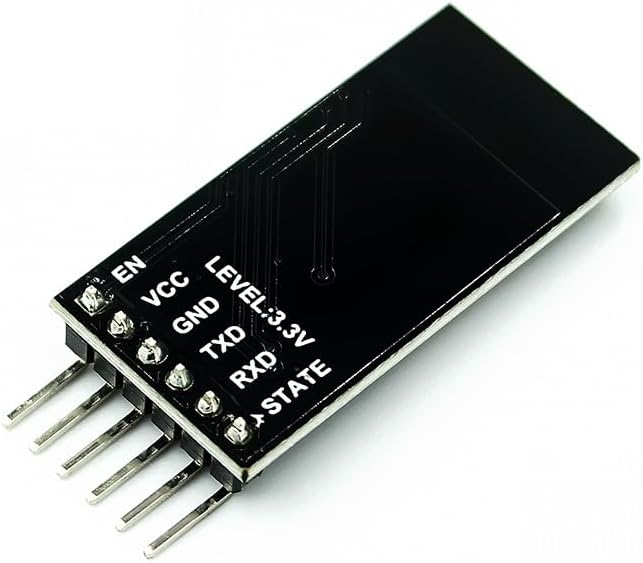
Figure 2.2: Bottom view of the DT-06 module, illustrating the pin labels for connection.
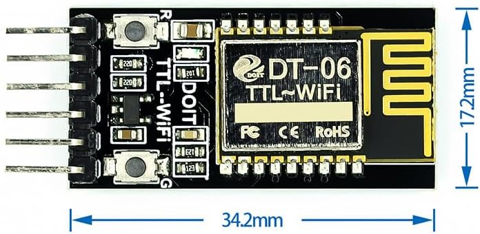
Figure 2.3: Dimensions of the DT-06 module, showing its compact size (34.2mm x 17.2mm).
3. Features
- Versatile Connectivity: Seamlessly converts TTL signals to WiFi, allowing easy integration with various microcontrollers and devices.
- Bluetooth Compatibility: Designed to work with Bluetooth HC-06 interfaces for flexible communication.
- User-Friendly Setup: Straightforward installation and configuration with a WEB interface.
- Reliable Performance: Ensures stable and reliable data transmission over WiFi.
- Compact Design: Lightweight and compact form factor (34mm × 17mm × 4mm).
- Firmware: Built-in industrial-grade transparent transmission firmware V3.0.
- Power Supply: 4.5V~6.0V, TTL voltage: 3.3V (compatible with 5.0V).
- Low Power Consumption: Average current: 80mA; 170mA when WiFi data is sent; 20μA in deep sleep mode.
- AT Commands: Supports serial port AT commands for configuration.
- OTA Firmware Upgrade: Supports reprogrammable and OTA firmware upgrades.
- Transparent Transmission: Real-time seamless transparent transmission of serial port and WiFi data.
- Web Server: Built-in HTTP Web Server for web page configuration.
- WiFi Modes: Supports AP, STA, AP+STA modes.
- Auto Reconnection: Supports automatic reconnection in WiFi STA mode and TCP Client mode.
- Serial Port Settings: Configurable baud rate, data bit, parity, stop bit, and packet time.
- Baud Rates: Supports a wide range of baud rates from 300 to 3686400 bps.
- Network Configuration: Custom SSID/password, IP, and network segment for AP mode; automatic hotspot scanning, DHCP, custom IP for STA mode.
- Protocols: Supports TCP Server, TCP Client, UDP Server, UDP Client, and UDP LAN broadcast.
- DNS Resolution: Remote server address supports automatic DNS domain name resolution.
- Status Indication: IO4 pin indicates WiFi status.
- Operating Temperature: -40℃ to 125℃.
4. What's in the Box
- 1PC DT-06 Wireless WiFi Serial Module
5. Setup Guide
5.1 Pin Description
The DT-06 module has several pins for power, serial communication, and control. Refer to the pinout diagram (Figure 2.2) for exact locations.
| Pin Name | Description |
|---|---|
| EN | Enable pin. High to enable the module. |
| VCC | Power supply input (4.5V~6.0V). |
| GND | Ground. |
| TXD | Transmit Data (TTL 3.3V, 5.0V compatible). Connect to RXD of your microcontroller/device. |
| RXD | Receive Data (TTL 3.3V, 5.0V compatible). Connect to TXD of your microcontroller/device. |
| STATE | WiFi status indicator pin (IO4). |
5.2 Initial Connection
- Power Supply: Connect VCC to a 4.5V-6.0V power source and GND to ground.
- Serial Connection: Connect the module's TXD to your microcontroller's RXD, and the module's RXD to your microcontroller's TXD. Ensure voltage compatibility (3.3V or 5.0V).
- Enable Pin: Connect the EN pin to VCC or a high logic level to enable the module.
- Status LED: Observe the STATE pin (IO4) for WiFi status indication.
Once powered, the module will typically enter a default mode, often AP mode, allowing initial configuration via a web interface or AT commands.
6. Operating Instructions
6.1 Configuration via Web Interface
The DT-06 module features a built-in HTTP Web Server for easy configuration. Follow these steps:
- Connect to Module's AP: On your computer or smartphone, scan for WiFi networks. The module will typically broadcast an SSID like "DT-06_XXXX" or similar. Connect to this network.
- Access Web Interface: Open a web browser and navigate to the module's default IP address (e.g., 192.168.4.1).
- Configure Settings: From the web interface, you can configure various parameters including:
- WiFi Mode (AP, STA, AP+STA)
- STA Mode: Connect to an existing WiFi network (SSID, password)
- Serial Port Parameters (Baud Rate, Data Bits, Parity, Stop Bits)
- Network Protocol (TCP Server/Client, UDP Server/Client)
- Remote Server IP/Port (for TCP/UDP Client)
- Save and Restart: After making changes, save the configuration and restart the module for changes to take effect.
6.2 Configuration via AT Commands
The module also supports configuration using AT commands sent over the serial port. A serial terminal program (e.g., PuTTY, Termite) is required.
- Connect Serial Port: Ensure your microcontroller or USB-to-TTL converter is correctly connected to the module's TXD/RXD pins.
- Open Serial Terminal: Configure your serial terminal with the correct baud rate (default is often 115200 or 9600) and other serial parameters (8 data bits, no parity, 1 stop bit).
- Send AT Commands: Send AT commands to query or set parameters. For example:
AT- Test command, should return "OK".AT+CWMODE=1- Set WiFi mode to STA.AT+CWJAP="SSID","Password"- Connect to an access point.AT+UART=115200,8,1,0,0- Set serial port baud rate to 115200.
- Refer to Documentation: For a complete list of AT commands and their syntax, refer to the detailed AT command set documentation (not provided in this manual, typically available from the manufacturer).
6.3 Data Transparent Transmission
The primary function of the DT-06 module is transparent data transmission. Once configured, any data sent to the module's serial port will be transmitted over WiFi (to a configured TCP/UDP server or client), and any data received over WiFi will be output through the serial port.
- Serial to WiFi: Data received on RXD is buffered and sent over the configured WiFi connection.
- WiFi to Serial: Data received over WiFi is output through the TXD pin.
7. Specifications
| Parameter | Value |
|---|---|
| Model | DT-06 |
| Base Module | ESP-M2 |
| Firmware | Industrial-grade transparent transmission firmware V3.0 |
| Overall Size | 34mm × 17mm × 4mm |
| Power Supply Voltage | 4.5V~6.0V |
| TTL Voltage | 3.3V (compatible with 5.0V) |
| Lead Pins | STATE, TXD, RXD, EN, VCC, GND |
| Average Current | 80mA |
| WiFi Data Send Current | 170mA |
| Deep Sleep Mode Current | 20μA |
| Serial Port Baud Rates | 300/600/1200/2400/4800/9600/19200/38400/57600/74800/115200/230400/460800/921600/1843200/3686400 bps |
| WiFi Modes Supported | AP, STA, AP+STA |
| Protocols Supported | TCP Server, TCP Client, UDP Server, UDP Client, UDP LAN broadcast |
| Operating Temperature Range | -40℃ to 125℃ |
| Item Weight | 1.06 ounces |
| Package Dimensions | 5.12 x 3.15 x 1.18 inches |
8. Troubleshooting
- Module Not Powering On:
Solution: Verify power supply voltage (4.5V-6.0V) and ensure correct polarity. Check all power connections (VCC, GND).
- Cannot Connect to Module's AP:
Solution: Ensure the module is powered on and in AP mode. Try resetting the module. Check if other devices can see the AP. Ensure no other WiFi networks are interfering.
- Web Interface Not Loading:
Solution: Confirm you are connected to the module's WiFi network. Double-check the IP address (default is often 192.168.4.1). Clear browser cache or try a different browser.
- AT Commands Not Responding:
Solution: Verify serial port connections (TXD to RXD, RXD to TXD). Ensure the serial terminal settings (baud rate, data bits, parity, stop bits) match the module's configuration. Check if the module is in AT command mode (if applicable, some modules require a specific pin state or command to enter AT mode).
- Data Transmission Issues:
Solution:
- For STA mode, ensure the module is successfully connected to your router (check STATE pin or web interface).
- Verify TCP/UDP server/client settings (IP address, port).
- Check serial port baud rates on both the module and the connected device.
- Ensure no firewall or network issues are blocking communication.
- Module Overheating:
Solution: Ensure the power supply voltage is within the specified range. Provide adequate ventilation around the module. Reduce the load if possible.
9. Maintenance
The DT-06 Wireless WiFi Serial Module is designed for robust operation and requires minimal maintenance. Follow these guidelines to ensure its longevity:
- Keep Dry: Avoid exposure to moisture or liquids, which can damage electronic components.
- Cleanliness: Keep the module free from dust and debris. Use a soft, dry brush or compressed air for cleaning if necessary. Do not use liquid cleaners.
- Temperature: Operate the module within its specified temperature range (-40℃ to 125℃). Avoid extreme heat or cold.
- Power Supply: Always use a stable power supply within the recommended voltage range (4.5V~6.0V). Over-voltage can cause permanent damage.
- Firmware Updates: Periodically check the manufacturer's website for firmware updates. Updating firmware can improve performance, add features, or fix bugs. Follow update instructions carefully.
- Physical Handling: Handle the module by its edges to avoid touching sensitive components. Protect it from physical shocks or drops.
10. Warranty and Support
Information regarding product warranty and specific support contacts is not available in the provided product data. Please refer to the seller or manufacturer's official website for details on warranty terms, technical support, and customer service.
For general inquiries or troubleshooting not covered in this manual, consider consulting online forums or communities dedicated to ESP-M2 or similar WiFi modules, as they often provide valuable insights and solutions.