1. Introduction
This manual provides comprehensive instructions for the installation, operation, and maintenance of the EJWFASCV PCD-33A-A/M BK Temperature Control Meter. This device is designed for precise temperature regulation in various industrial and household applications.
Key Features:
- Temperature control with long service life.
- Wide range of applications, suitable for household appliances and industrial equipment.
- Convenient installation and easy maintenance, offering reliable precision.
2. Safety Information
Please read all safety warnings and instructions carefully before installing or operating this device. Failure to follow these instructions may result in electric shock, fire, or serious injury.
- Ensure power is disconnected before any installation or wiring.
- Installation should be performed by qualified personnel.
- Do not operate the device in environments exceeding its specified temperature and humidity limits.
- Verify all wiring connections are secure and correct according to the wiring diagram.
3. Product Overview
The PCD-33A-A/M BK features a clear digital display and intuitive controls for precise temperature management.

Figure 3.1: Front view of the PCD-33A-A/M BK Temperature Controller, showing the digital display for PV (Process Value) and SV (Set Value), along with control buttons for PTN, STEP, RST, MODE, RUN, and STOP.
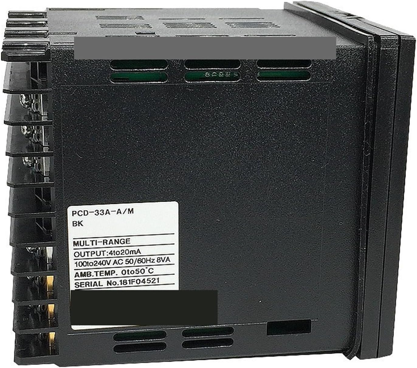
Figure 3.2: Side view of the PCD-33A-A/M BK, displaying the product label with model number PCD-33A-A/M BK, output specifications (4-20mA), working voltage (100-240V AC 50/60Hz), ambient temperature range (0 to 50°C), and serial number.

Figure 3.3: Rear view of the PCD-33A-A/M BK, showing the terminal block and detailed wiring diagram for power supply (100-240V AC), RS-485 communication, output (OUT), alarm outputs (A1, A2), and sensor inputs (TC, RTD).
Display and Buttons:
- PV (Process Value): Displays the current measured temperature.
- SV (Set Value): Displays the target temperature.
- PTN/STEP: Program and step control buttons.
- RST: Reset button.
- MODE: Mode selection button for navigating menus.
- RUN/STOP: Start and stop operation.
- Up/Down Arrows: Adjust values and navigate options.
4. Specifications
| Parameter | Value |
|---|---|
| Model | PCD-33A-A/M BK |
| Control Type | Smart Temperature Control Regulator |
| Temperature Range | -200 to 1370 ℃ (Other ranges like 0-400℃, 0-1600℃ available) |
| Temperature Measurement Error | Accuracy 0.2% |
| Sampling Cycle | 0.25 seconds |
| Hole Size (W x H) | 92mm x 92mm |
| Installation Type | Buckle Installation |
| Output Signal | 4-20mA DC current output (can drive power regulator, voltage regulator module) |
| Working Voltage | 100-240V AC |
| Overall Dimensions (W x H) | 96mm x 96mm |
| Item Weight | 10.6 ounces (approx. 300g) |
5. Installation
5.1 Mounting
The PCD-33A-A/M BK is designed for buckle installation into a panel cutout. Ensure the panel hole size is 92mm wide by 92mm high for a secure fit.
- Cut a square opening of 92mm x 92mm in the desired panel.
- Insert the temperature controller into the opening from the front.
- Secure the device using the provided buckle clips from the rear of the panel.
5.2 Wiring
Refer to Figure 3.3 (Rear view with wiring diagram) for detailed terminal connections. Ensure all connections are made correctly and securely to prevent damage or malfunction.
- Power Supply (100-240V AC): Connect the main power supply to the designated terminals.
- Sensor Input: Connect your temperature sensor (Thermocouple or RTD) to the appropriate input terminals. Ensure correct polarity for thermocouples.
- Output (4-20mA): Connect the control output to your power regulator, voltage regulator module, or other controlled device.
- Alarm Outputs (A1, A2): If utilizing alarm functions, connect external alarm devices to these terminals.
- RS-485 (Optional): For communication with other systems, connect RS-485 lines to the corresponding terminals.
Caution: Incorrect wiring can damage the device and connected equipment. Always double-check connections before applying power.
6. Operation
6.1 Basic Power On
After successful installation and wiring, apply power to the device. The display will illuminate, showing the current Process Value (PV) and Set Value (SV).
6.2 Setting the Set Value (SV)
- Press the MODE button to enter the parameter setting mode.
- Use the Up or Down arrow buttons to navigate to the SV parameter.
- Press MODE again to select the SV for editing.
- Use the Up or Down arrow buttons to adjust the desired temperature.
- Press MODE to confirm the new SV and exit the setting mode.
6.3 Running and Stopping Control
- To start temperature control, press the RUN button. The controller will begin regulating the temperature according to the SV.
- To stop temperature control, press the STOP button. The output will be deactivated.
6.4 Advanced Settings (PID Tuning, Alarms)
For advanced settings such as PID auto-tuning, alarm configurations, and input type selection, refer to the detailed programming guide (if available) or contact technical support. These settings are typically accessed via specific button combinations or menu navigation using the MODE and arrow buttons.
7. Maintenance
The EJWFASCV PCD-33A-A/M BK is designed for low maintenance. Regular checks can ensure optimal performance and longevity.
- Cleaning: Gently wipe the display and casing with a soft, dry cloth. Do not use abrasive cleaners or solvents.
- Connections: Periodically check all wiring connections for tightness and signs of corrosion.
- Environment: Ensure the operating environment remains within specified temperature and humidity ranges to prevent damage.
- Sensor Check: If temperature readings appear inaccurate, inspect the temperature sensor and its wiring for damage or loose connections.
Warning: Disconnect power before performing any maintenance or cleaning.
8. Troubleshooting
This section addresses common issues you might encounter with the temperature controller.
| Problem | Possible Cause | Solution |
|---|---|---|
| Display is blank | No power supply; Incorrect wiring; Device fault. | Check power connection and voltage; Verify wiring according to diagram; Contact support if power is present and wiring is correct. |
| Inaccurate temperature reading | Sensor faulty or disconnected; Incorrect sensor type selected; Sensor not properly installed. | Check sensor wiring and connection; Ensure sensor type matches controller settings; Re-install sensor correctly. |
| Controller not regulating temperature | Output not enabled; Incorrect control parameters (e.g., PID settings); Wiring issue to controlled device. | Ensure controller is in RUN mode; Review and adjust control parameters; Check wiring to heater/cooler. |
| Buttons unresponsive | Temporary software glitch; Hardware fault. | Try power cycling the device; If issue persists, contact technical support. |
9. Warranty and Support
This product is covered by a standard manufacturer's warranty against defects in materials and workmanship. For specific warranty terms and conditions, please refer to the product packaging or contact your point of purchase.
For technical support, troubleshooting assistance, or inquiries regarding spare parts, please contact EJWFASCV customer service. Have your product model number (PCD-33A-A/M BK) and serial number ready when contacting support.
Contact Information:
Please refer to the manufacturer's official website or your purchase documentation for the most current contact details.


