1. Introduction and Overview
The Irfora 150A MPPT Solar Controller is an advanced intelligent regulator designed to optimize the charging process of batteries in solar power systems. It is compatible with 12V, 24V, 36V, and 48V battery systems and supports various battery types including lithium-ion, lithium iron phosphate (LiFePO4), and acid batteries. Utilizing Maximum Power Point Tracking (MPPT) technology, this controller ensures efficient energy harvest from your solar panels, extending battery lifespan and enhancing overall system performance. It features a clear LCD display for real-time monitoring and dual USB outputs for convenient device charging.
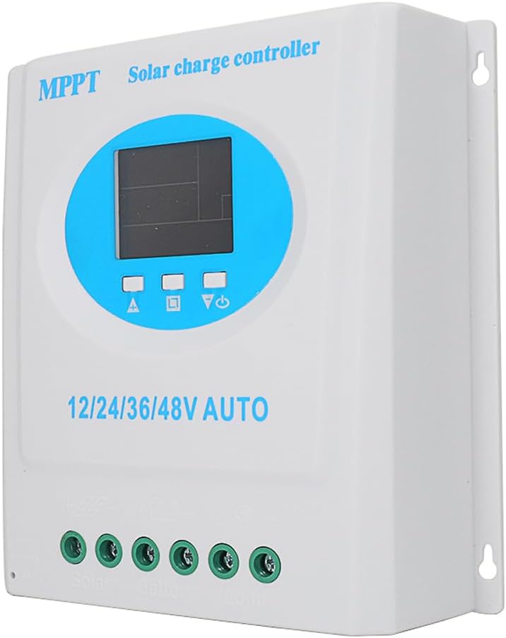
Figure 1.1: Front view of the Irfora 150A MPPT Solar Controller, showing the LCD display and connection terminals.
2. Key Features
- Universal Voltage Compatibility: Automatically detects and supports 12V, 24V, 36V, and 48V battery systems.
- Wide Battery Type Support: Compatible with lithium-ion, lithium iron phosphate (LiFePO4), and acid batteries.
- Maximized Charging Efficiency: Employs MPPT technology for quick and efficient charging, optimizing energy harvest from solar panels.
- Versatile Operating Modes: Offers multiple modes including auto, light-controlled, test, manual, timer, universal, and light-controlled with delay for flexible energy management.
- Comprehensive Safety Features: Built-in protections against overvoltage, overcurrent, overtemperature, overload, and short circuits. Automatic disconnect prevents overcharging.
- Intuitive LCD Display: Provides real-time information on output voltage, battery level, mode status, and system health.
- Dual USB Charging Ports: Conveniently power smartphones, tablets, and cameras directly from your solar system.
- Automatic Memory Data Storage: Ensures smooth operation and retains settings during power cycles.
3. Safety Information
Please read and understand all safety instructions before installing or operating the solar controller. Failure to follow these instructions may result in electric shock, fire, or serious injury.
- Ensure all connections are secure and correctly polarized to prevent damage to the controller, battery, or solar panels.
- Do not attempt to disassemble or repair the controller yourself. Refer to qualified personnel for service.
- Install the controller in a well-ventilated area, away from flammable materials and direct sunlight.
- Protect the controller from water and excessive humidity.
- Always disconnect the solar panel and battery power before performing any maintenance or wiring changes.
- The controller is equipped with internal protection mechanisms against overvoltage, overcurrent, overtemperature, overload, and short circuits. However, proper system design and external fusing are recommended for enhanced safety.
4. Product Components and Package Contents
The package for your Irfora 150A MPPT Solar Controller should contain the following items:
- 1 x Irfora 150A MPPT Solar Controller
- 1 x User's Manual (this document)
Please inspect all components upon receipt to ensure they are present and undamaged.
5. Setup and Installation
Follow these steps for proper installation of your solar charge controller. Ensure all power sources are disconnected before beginning wiring.
- Mounting: Choose a suitable location for mounting the controller. It should be indoors, dry, well-ventilated, and protected from direct sunlight and extreme temperatures.
- Battery Connection: Connect the battery to the controller first. Ensure correct polarity: connect the positive (+) terminal of the battery to the battery positive terminal on the controller, and the negative (-) terminal of the battery to the battery negative terminal on the controller. This step is crucial for the controller to detect the system voltage.
- Solar Panel Connection: Connect the solar panel(s) to the controller. Connect the positive (+) terminal of the solar panel array to the solar panel positive terminal on the controller, and the negative (-) terminal to the solar panel negative terminal on the controller.
- Load Connection (Optional): If you are connecting a DC load directly to the controller, connect the load to the load terminals on the controller, ensuring correct polarity.

Figure 5.1: Wiring diagram showing connections for solar panel, battery, and DC load to the solar charge controller.
Important: Always connect the battery first, then the solar panel, and finally the load. Disconnect in the reverse order: load, then solar panel, then battery.
6. Operating Instructions
6.1 LCD Display Overview
The clear LCD display provides real-time information about your solar system's status.

Figure 6.1: Detailed view of the LCD display, indicating battery level, solar panel charging, load identification, mode control, and normal/fault display areas.
- Battery Level Marking: Indicates the current charge level of the connected battery.
- Solar Panel Charging Marking: Shows the current input from the solar panels.
- Load Identification: Displays the status of the connected DC load.
- Mode Control Display Area: Allows selection and display of various operating modes.
- Normal/Fault Display Area: Indicates normal operation or displays error codes if a fault occurs.
6.2 Operating Modes
The controller offers multiple operating modes to suit different application needs. These modes can be selected via the display interface.

Figure 6.2: The controller's interface showing options for selecting various operating modes.
- Auto Mode: Standard automatic operation.
- Light-Controlled Mode: Load output is controlled by ambient light levels (e.g., turns on at dusk, off at dawn).
- Test Mode: For testing purposes.
- Manual Mode: Allows manual control of the load output.
- Timer Mode: Load output operates for a set duration.
- Universal Mode: General purpose mode.
- Light-Controlled with Delay Mode: Similar to light-controlled but with a customizable delay.
6.3 Dual USB Charging
The controller is equipped with dual USB ports (5V, 1A) for convenient charging of external devices such as smartphones, tablets, and cameras.
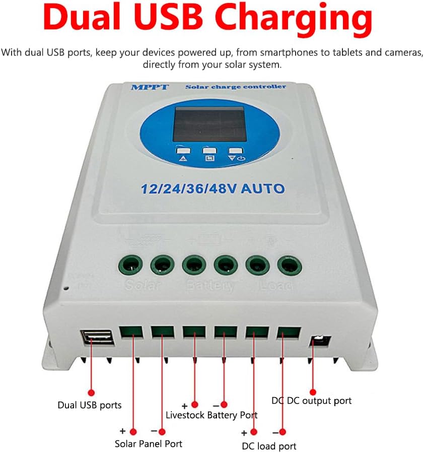
Figure 6.3: Close-up view of the dual USB charging ports located on the side of the controller.
7. Maintenance
Regular maintenance helps ensure the longevity and optimal performance of your solar charge controller.
- Cleaning: Periodically clean the controller's exterior with a dry, soft cloth to remove dust and dirt. Do not use liquid cleaners.
- Connection Check: Annually inspect all wiring connections to ensure they are tight and free from corrosion. Loose connections can cause overheating and poor performance.
- Visual Inspection: Check for any signs of physical damage, discoloration, or unusual odors. If any issues are observed, disconnect power immediately and consult a qualified technician.
- Ventilation: Ensure that the area around the controller remains clear to allow for proper airflow and heat dissipation.
8. Troubleshooting
If you encounter issues with your solar controller, refer to the following common problems and solutions.
| Problem | Possible Cause | Solution |
|---|---|---|
| Controller display is off / No power | Battery not connected or low voltage; reversed battery polarity; loose connections. | Check battery connections and voltage. Ensure battery is connected first and correctly. Tighten all terminals. |
| Battery not charging | Solar panel not connected or insufficient sunlight; reversed solar panel polarity; damaged solar panel or wiring. | Verify solar panel connections and polarity. Ensure adequate sunlight. Check solar panel output voltage. |
| Load not working | Load not connected or reversed polarity; battery voltage too low; overload protection activated; load mode setting incorrect. | Check load connections and polarity. Ensure battery has sufficient charge. Reduce load. Adjust operating mode settings. |
| Error code on display | Specific system fault (e.g., overvoltage, short circuit). | Refer to the controller's specific error code definitions (if available in a more detailed manual) or disconnect all power, wait a few minutes, and reconnect. Address the underlying issue (e.g., reduce voltage, fix short). |
If the problem persists after attempting these solutions, please contact customer support.
9. Specifications
Detailed technical specifications for the Irfora 150A MPPT Solar Controller:
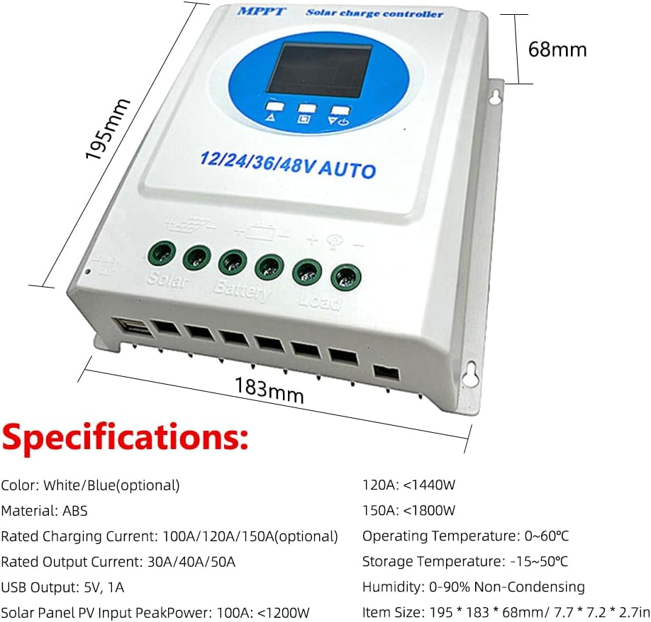
Figure 9.1: Diagram illustrating the physical dimensions and a summary of key specifications.
| Parameter | Value |
|---|---|
| Rated Charging Current | 150A (also available in 100A/120A variants) |
| Rated Output Current | 50A (also available in 30A/40A variants) |
| USB Output | 5V, 1A (Dual USB ports) |
| Solar Panel PV Input Peak Power (for 150A) | <1800W |
| Operating Temperature | 0℃ ~ 60℃ (32℉ ~ 140℉) |
| Storage Temperature | -15℃ ~ 50℃ (5℉ ~ 122℉) |
| Humidity | 0-90% Non-Condensing |
| Material | ABS |
| Item Size | 195 x 183 x 68 mm (7.7 x 7.2 x 2.7 inches) |
| Package Size | 205 x 205 x 70 mm (8.1 x 8.1 x 2.8 inches) |
| Package Weight (for 150A) | 900g (31.7oz) |
10. Warranty and Support
For warranty information and customer support, please refer to the purchase documentation or contact the seller/manufacturer directly.
Brand: Irfora
For technical assistance or inquiries, please reach out to the official Irfora support channels.


