1. Introduction
The Irfora 623 Car Multimeter is a versatile digital multimeter designed for both automotive and general electrical applications. It features a 20000-count display and a wide range of measurement functions, including AC/DC voltage and current, resistance, capacitance, temperature, RPM, mS pulse, engine dwell angle, and Non-Contact Voltage (NCV) detection. This manual provides essential information for the safe and effective operation of your device.

Figure 1.1: Irfora 623 Car Multimeter with its foldable screen and control panel.
2. Safety Information
Always observe safety precautions when using electrical testing equipment. Failure to do so may result in injury or damage to the multimeter or the equipment under test.
- Overload Protection: The multimeter features full-range overload protection. However, avoid exceeding the specified maximum input values for each function.
- Non-Contact Voltage (NCV) Detection: Use the NCV feature to detect the presence of voltage without direct contact, enhancing safety.
- Live Wire/Diode Test: Exercise extreme caution when performing live wire tests. Ensure proper connection and follow all instructions.
- Battery Safety: Use only the specified charging cable and power source for the built-in rechargeable battery. Do not attempt to open or replace the battery.
- Environmental Conditions: Do not operate the multimeter in wet conditions or explosive atmospheres.
3. Product Overview
3.1 Key Features
- 20000 Counts Digital Display
- 5.15-inch 180° Foldable Screen for easy viewing
- Versatile Measurement Functions: AC/DC Voltage, AC/DC Current, Resistance, Capacitance, Temperature
- Specialized Automotive Functions: RPM (Revolutions Per Minute), mS Pulse (Pulse Width), Engine Dwell Angle
- Safety Features: NCV (Non-Contact Voltage) Detection, Live Wire/Diode Test, Full-range Overload Protection
- Built-in 3.7V 1800mAh Rechargeable Lithium Battery
3.2 LCD Display Analysis
The LCD provides clear readings and indicators for various functions. Refer to the diagram below for an explanation of common display icons.

Figure 3.1: Explanation of LCD display icons, including MAX/MIN, AC/DC, NCV, Live, Dwell Angle, RPM, and more.
4. Setup
4.1 Initial Charging
Before first use, fully charge the multimeter's built-in 3.7V 1800mAh lithium battery using the provided USB Type-C charging cable. Connect the cable to the multimeter's charging port and a suitable USB power adapter.
4.2 Connecting Test Leads
Insert the red test lead into the 'VΩmA' or '10A' input jack, depending on the measurement function. Insert the black test lead into the 'COM' (common) input jack. Ensure connections are secure before proceeding with any measurements.
5. Operating Instructions
Turn on the multimeter by pressing the power button. Select the desired measurement function using the function buttons on the control panel.
5.1 General Measurement Functions

Figure 5.1: Examples of AC/DC Voltage, Temperature, Diode, and Capacitance measurements.

Figure 5.2: Examples of Resistance, DC Current, AC Current, and Continuity (Buzzer) measurements.
- AC/DC Voltage: Switch to the V~ (AC) or V- (DC) gear. Connect test leads in parallel to the circuit.
- AC/DC Current: Switch to the mA~ (AC) or mA- (DC) gear, or 10A gear for higher currents. Connect test leads in series with the circuit.
- Resistance: Switch to the Ω gear. Connect test leads across the component.
- Capacitance: Switch to the F gear. Connect test leads across the capacitor.
- Temperature: Connect the temperature probe to the multimeter and place the probe tip on the object to be measured.
- Diode Test: Switch to the diode symbol gear. Connect the red lead to the anode and black lead to the cathode of the diode.
- Continuity Test: Switch to the buzzer symbol gear. The multimeter will beep if continuity is detected.
5.2 Specialized Automotive Functions
- RPM (Engine Speed) Test:
Press the RPM function key. Connect the red lead to the ignition system's tach signal line (e.g., distributor ignition or primary ignition coil) and the black lead to a good ground terminal of the car battery. Start the engine and read the RPM value on the display. Select the appropriate engine stroke (2-stroke or 4-stroke) if applicable.

Figure 5.3: Steps for performing an RPM engine speed test.
- mS Pulse (Pulse Width) Measurement:
Switch to the mS PULSE gear. Connect the black test lead to the fuel injector ground or a good car ground. Connect the red test lead (or electromagnetic drive input line) to the fuel injector signal line. Start the engine and measure the pulse width time.

Figure 5.4: Measuring car pulse width on a fuel injector.
- Engine Dwell Angle Measurement:
Press the Dwell Angle function key. Connect the test leads to the open circuit switch of the ignition system. Select the appropriate number of cylinders (1-8 CYL) for accurate measurement.
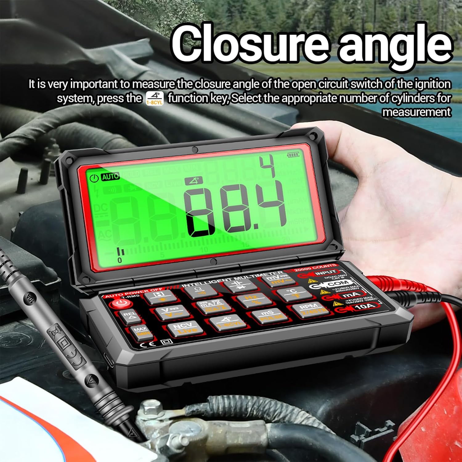
Figure 5.5: Measuring engine dwell angle.
5.3 NCV (Non-Contact Voltage) Detection
When AC voltage is detected near the multimeter's NCV sensor (typically on the back), the meter will emit a buzzer alarm, and the LCD analog bar will display the induction intensity. This feature allows for voltage detection without direct contact, enhancing safety.

Figure 5.6: NCV (Non-Contact Voltage) detection in progress.
5.4 Live Wire Test
In Live mode, the multimeter distinguishes between live and zero lines. The live line will trigger an alarm, while the zero line will not respond. This helps in identifying live circuits.

Figure 5.7: Live wire testing using the multimeter.
6. Maintenance
- Cleaning: Wipe the multimeter with a damp cloth. Do not use abrasive cleaners or solvents.
- Battery Charging: Recharge the built-in battery when the low battery indicator appears on the display.
- Storage: Store the multimeter in a cool, dry place away from direct sunlight and extreme temperatures. If storing for extended periods, ensure the battery is partially charged.
7. Troubleshooting
- No Power: Ensure the battery is charged. If the device does not turn on, try charging it for at least 30 minutes.
- "OL" Display: This indicates an overload or out-of-range measurement. Check your connections and ensure the measurement range is appropriate for the value being measured.
- Inaccurate Readings: Verify test lead connections are secure and undamaged. Ensure the correct function and range are selected.
- No NCV Detection: Ensure the NCV sensor area is clear and not obstructed. Factors such as socket design and insulation thickness can affect detection.
8. Specifications
| Parameter | Value |
|---|---|
| Brand | ANENG (Irfora) |
| Product Material | ABS |
| Display | LCD |
| Maximum Count | 19999 |
| Polarity Indication | Automatic, '-' Indicates Negative Polarity |
| Over Range Display | 'OL' or '- OL' |
| Sampling Rate | Approximately 2 Times Per Second |
| Unit Display | Function Display, Battery Display |
| Automatic Shutdown Time | Approximately 15 Minutes |
| Power Supply | 3.7V/1800mAh Lithium Battery |
| Working Temperature | 0 ℃ - 40 ℃ |
| Storage Temperature | -20 ℃ - 60 ℃ |
| Product Size | 14.7 x 8.6 x 3.72 cm (5.78 x 3.38 x 1.46 inches) |
| Product Dimensions (L x W x H) | 7.28 x 4.25 x 2.76 inches |
9. Package Contents
The following items are included in your Irfora 623 Car Multimeter package:
- 1x Digital Multimeter (Irfora 623)
- 1x Test Line (Red/Black Test Leads)
- 1x Temperature Probe
- 1x 16-in-1 Combination Line (additional probes/adapters)
- 1x USB Type-C Charging Cable
- 1x Storage Bag
- 1x User Manual (this document)

Figure 9.1: All items included in the product package.
10. Warranty and Support
For warranty information and technical support, please refer to the documentation provided at the time of purchase or contact your retailer. Keep your purchase receipt as proof of purchase.


