
1. Introduction
The DEWIN VFD Frequency Converter is an advanced motor speed controller designed to efficiently manage the operation of three-phase AC motors. This 2.2kW model is engineered to convert a single-phase 220V input into a three-phase 380V output, providing precise control over motor speed and torque. It is suitable for a wide range of industrial and commercial applications requiring variable speed control.
2. Safety Information
WARNING: Always read this user manual thoroughly before operating the device. Failure to follow safety instructions can result in electrical shock, equipment damage, or personal injury.
- Electrical Shock Hazard: This device operates with high voltage. Ensure all power is disconnected before installation, maintenance, or troubleshooting.
- Discharge Time: After disconnecting power, wait at least 10 minutes for internal capacitors to discharge before touching any components.
- Qualified Personnel: Installation and servicing should only be performed by qualified electricians or technicians.
- Proper Grounding: Ensure the device is properly grounded according to local electrical codes.
- Environmental Conditions: Do not expose the converter to moisture, excessive dust, or corrosive environments.
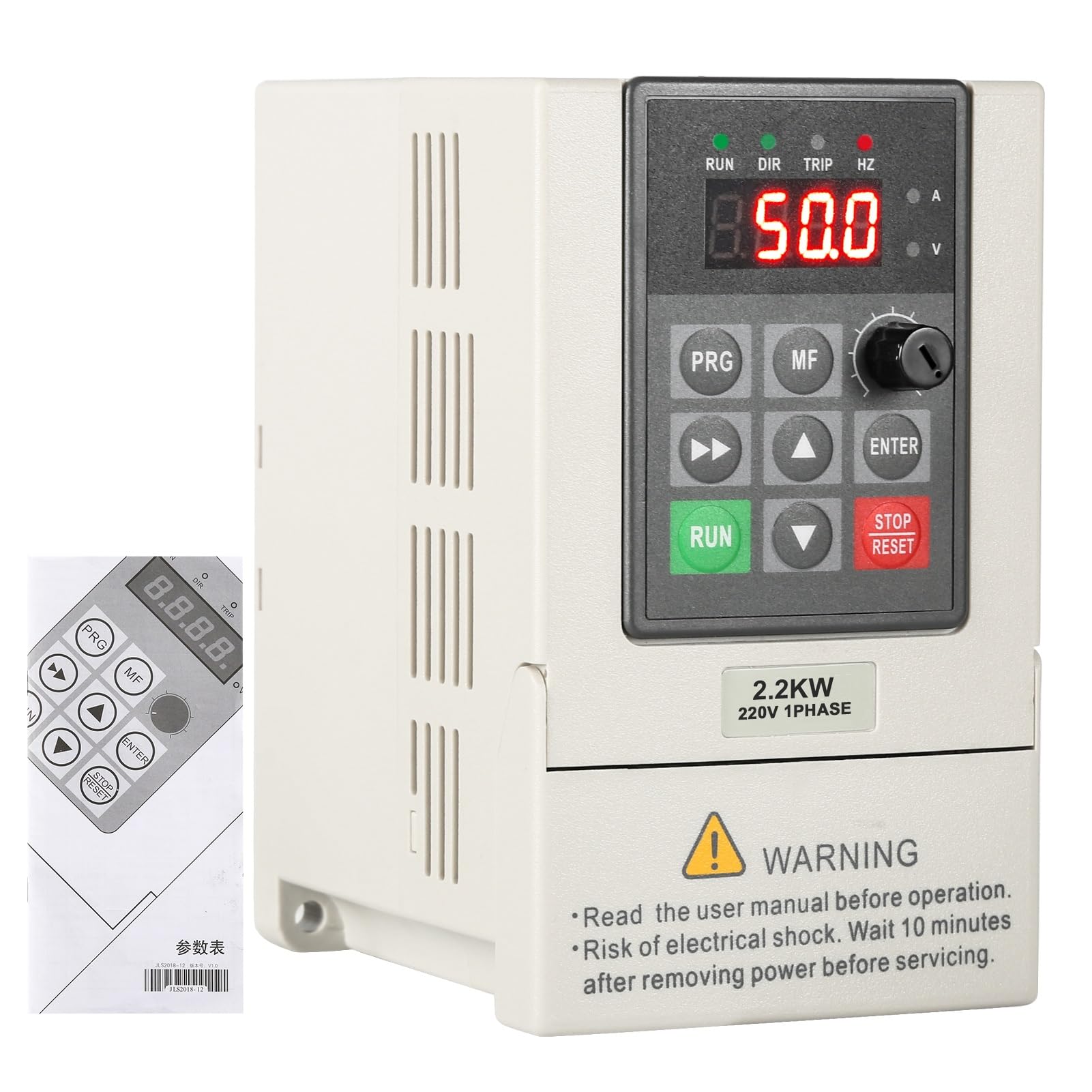
Image: Front view of the DEWIN VFD Frequency Converter, showing the display, control buttons, and a warning label regarding electrical shock and discharge time.
3. Product Overview and Features
The DEWIN VFD Frequency Converter is equipped with several features to ensure reliable and efficient motor control:
- High Performance: Utilizes a unique control method to achieve high power, high torque, high precision, and a wide range of speed control.
- Communication Port: Includes a 485 communication port for integration into control systems.
- Robust Design: Features a double-layer board configuration (power board + motherboard) for enhanced stability and durability.
- Comprehensive Protection: Incorporates nine protection technologies including overvoltage, undervoltage, over-current, overload, over-temperature, power module protection, grounding, short circuit, and stagnation protection.
- Efficient Cooling: Equipped with an intelligent fast radiator and air-cooled fan control for effective heat dissipation and silent operation.
- User-Friendly Interface: Simple operation with convenient wiring and one-click parameter settings. Features a high-definition screen for intuitive data display.
- Stable Output: Provides stable and continuous pure sine wave output with a built-in AVR stabilizer.
- Advanced Module Design: IPM and IGBT module design improves efficiency, reduces heat generation, and ensures stable quality.
- Environmental Adaptability: Offers good anti-interference performance, adapting well to cold temperatures, humidity, and dusty environments.

Image: The DEWIN VFD Frequency Converter with text overlays indicating key features such as 'Protect The Motor', 'Energy Saving', 'Frequency', and 'Strong Security'.

Image: A close-up view of the VFD's side, showing the integrated radiator and cooling fan, with arrows illustrating airflow for heat dissipation.
4. Specifications
| Model | QYABEEAEC-GS110622-03 |
| Material | ABS flame retardant process |
| Color | White |
| Nominal Input Voltage | Single phase 220V |
| Nominal Output Voltage | Three-phase 380V |
| Rated Power | 2.2 kW |
| Output Current | 5A (for 2.2kW model) |
| Factory Frequency | 50/60Hz |
| Output Frequency Range | 0-999Hz |
| Installation Method | Wall-mounted, Cabinet mounted |
| Dimensions (L x W x H) | 23 x 17 x 16 cm (approximate) |
| Cooling Method | Air-cooled, with fan control |
| Protection Level | IP20 |

Image: A visual representation of the product specifications, including model, material, color, voltage, power, frequency, and installation details.

Image: Diagram showing the physical dimensions of the DEWIN VFD Frequency Converter, with measurements of 230mm height, 160mm width, and 170mm depth.
5. Setup and Installation
Proper installation is crucial for the safe and efficient operation of the VFD. Refer to the detailed wiring diagrams and follow these general guidelines:
5.1 Mounting
- The converter can be wall-mounted or cabinet-mounted.
- Ensure adequate ventilation around the unit to facilitate proper cooling. Avoid mounting in enclosed spaces without airflow.
- Mount the unit vertically to optimize heat dissipation.
- Keep the unit away from direct sunlight, heat sources, and vibrating machinery.
5.2 Wiring
All wiring must comply with local and national electrical codes. Use appropriate wire gauges for the rated current.

Image: Simplified wiring diagram showing single-phase 220V input (L1, L2), ground connection (P, PB), and three-phase 380V output to a motor (U, V, W).

Image: Detailed wiring schematic illustrating control terminals (X1-X5), analog inputs (AO, AV1), communication ports (485+), and power connections for the VFD.
- Input Power (L1, L2): Connect the single-phase 220V AC power supply to the L1 and L2 terminals.
- Ground (P, PB): Connect the protective earth ground to the designated ground terminal. This is critical for safety.
- Motor Output (U, V, W): Connect the three-phase motor to the U, V, and W output terminals. Ensure correct phase sequence for desired motor rotation.
- Control Terminals: The VFD features various control terminals (e.g., X1-X5 for multi-function inputs, analog inputs for speed reference, 485 communication) for external control and monitoring. Refer to the detailed wiring schematic for specific connections.

Image: The DEWIN VFD with its control panel detached, illustrating the ease of access to wiring terminals for installation and maintenance.
6. Operating Instructions
The DEWIN VFD features an intuitive control panel for easy operation and parameter setting.
6.1 Control Panel Overview
The front panel includes a digital display, function buttons (PRG, MF, RUN, STOP/RESET), arrow keys (up, down, left, right), and an ENTER button. A rotary knob is also present for fine-tuning parameters or speed.
6.2 Basic Operation
- Power On: After ensuring all wiring is correct and secure, apply single-phase 220V power to the VFD. The display will illuminate.
- Parameter Setting: Press the 'PRG' button to enter the parameter setting mode. Use the arrow keys to navigate through parameters and the rotary knob or arrow keys to adjust values. Press 'ENTER' to confirm changes. The VFD supports one-click setting for common configurations.
- Start Motor: Press the 'RUN' button to start the motor. The display will show the current output frequency or other selected operating parameters.
- Adjust Speed: While the motor is running, use the rotary knob or designated arrow keys to adjust the output frequency, thereby changing the motor speed.
- Stop Motor: Press the 'STOP/RESET' button to stop the motor. This button also serves to reset any fault conditions.
For detailed parameter descriptions and advanced functions, refer to the comprehensive programming guide provided with the product or available from the manufacturer.
7. Maintenance
Regular maintenance ensures the longevity and optimal performance of your DEWIN VFD Frequency Converter.
- Power Disconnection: Always disconnect all power to the VFD and wait at least 10 minutes for internal capacitors to discharge before performing any maintenance or inspection.
- Cleaning: Keep the VFD clean and free from dust and debris. Use a soft, dry cloth for cleaning. Do not use liquid cleaners or solvents.
- Fan Inspection: Periodically check the cooling fan for obstructions or excessive dust buildup. Clean the fan blades and vents as necessary to ensure efficient airflow.
- Terminal Check: Inspect all wiring terminals for tightness and corrosion. Loose connections can lead to overheating and malfunction.
- Environmental Check: Ensure the operating environment remains within specified temperature, humidity, and dust levels (IP20 protection level).
8. Troubleshooting
The DEWIN VFD is equipped with multiple protection functions to indicate and prevent potential issues. If the VFD enters a fault state (indicated by a 'TRIP' light or error code on the display), follow these general troubleshooting steps:
- Identify Fault Code: Note any error codes displayed on the VFD's screen. Refer to the full user manual for a list of specific fault codes and their meanings.
- Reset Fault: Press the 'STOP/RESET' button to clear the fault. If the fault persists, do not attempt to restart the unit without further investigation.
- Check Power Supply: Verify that the input voltage is stable and within the specified range (single-phase 220V).
- Inspect Wiring: Ensure all power and motor connections are secure and correctly wired according to the diagrams in Section 5.2.
- Motor Check: Confirm that the motor is not overloaded, jammed, or experiencing any mechanical issues. Check motor winding resistance if possible.
- Environmental Factors: Ensure the VFD is not overheating due to poor ventilation or high ambient temperatures. Check for excessive dust or moisture.
- Protection Functions: The VFD includes protection against overvoltage, undervoltage, over-current, overload, over-temperature, power module issues, grounding faults, short circuits, and stagnation. An active protection indicates one of these conditions has been met.
If the problem cannot be resolved using these steps, contact qualified service personnel or DEWIN customer support.
9. Applications
The DEWIN VFD Frequency Converter is versatile and suitable for a wide range of applications requiring precise motor speed control and energy efficiency. Common applications include:
- Fans
- Water Pumps
- CNC Machine Tools
- Ball Mills
- Injection Molding Machines
- Crushers
- Belt Conveyors
- Textile Equipment

Image: A collage of images depicting various industrial equipment such as motors, water pumps, fans, blenders, air compressors, and conveyors, illustrating the wide applicability of the VFD.
10. Warranty and Support
For specific warranty terms and conditions, please refer to the documentation provided with your purchase or contact the seller directly. DEWIN provides technical support for its products. If you encounter any issues or require assistance beyond the scope of this manual, please reach out to DEWIN customer service or your authorized distributor.
