1. Introduction
This manual provides essential information for the safe and efficient operation of your DEWIN MS500-2S-2.2G Variable Frequency Drive (VFD). Please read this manual thoroughly before installation, operation, or maintenance to ensure proper use and prevent potential hazards. This VFD is designed to control the speed of three-phase asynchronous motors from a single-phase 220V input.
2. Safety Information
WARNING: Risk of electrical shock. Read the user manual before operation. Wait at least 10 minutes after removing power before servicing. Do not connect AC power to output terminals U/T1, V/T2, and W/T3.
Always observe the following safety precautions:
- Installation and wiring must be performed by qualified personnel only.
- Ensure the power supply is disconnected before any wiring or maintenance.
- Verify correct voltage and current ratings before connecting the VFD.
- Do not operate the VFD with damaged cables or components.
- Ensure proper grounding to prevent electrical shock.
- Keep the VFD away from moisture, direct sunlight, and corrosive environments.
- Do not touch internal components immediately after power-off, as residual voltage may be present.

Figure 2.1: Multi-language warning label indicating the need for adult supervision and caution with electrical components.
3. Product Features
The DEWIN MS500-2S-2.2G VFD offers advanced features for precise motor control:
- Multiple Control Algorithms: Supports asynchronous motor VF control, current vector open-loop control, permanent magnet synchronous motor standard open-loop control, and open-loop vector control. Provides 150% starting torque at 0.5Hz (sensorless vector control) for high torque, precision, and wide speed adjustment.
- Fast Current Limiting Function: Prevents frequent overcurrent alarms by quickly limiting current within the protection point when it exceeds the set threshold, safeguarding equipment from sudden charging or interference.
- High-Speed Cooling Fan: Features an independent heat dissipation duct and high-speed fan for effective cooling, reduced heat, low noise, and long-term stable operation.
- Torque Limit Protection: Limits output torque to a preset maximum to protect machinery when the command exceeds its mechanical capacity, ensuring equipment safety while maximizing efficiency.
- High-Quality Double-Layer Board: Equipped with an intelligent double-layer board (power board + main board) for high-speed processing. Features a large button design for simple operation and real-time data display on a digital screen.
- Compact Design: Small size with a detachable panel for easy installation and convenient screw terminal wiring.

Figure 3.1: Overview of the Variable Frequency Drive highlighting key benefits such as motor protection, energy saving, frequency control, and strong security.

Figure 3.2: The VFD is equipped with an independent cooling air duct and fan for efficient heat dissipation, ensuring stable long-term operation.
4. Specifications
Technical specifications for the DEWIN MS500-2S-2.2G VFD:
| Parameter | Value |
|---|---|
| Model Number | MS500-2S-2.2G |
| Material | Flame retardant ABS plastic |
| Nominal Input Voltage | Single phase 220V |
| Nominal Input Frequency | 50/60Hz |
| Nominal Output Voltage | Three-phase 220V |
| Rated Output Current | 10A |
| Applicable Motor Power | 2.2KW |
| Output Frequency (Low Frequency Mode) | 0-320Hz |
| Installation Method | Wall mounted |
| Protection Level | IP20 |
| Cooling Method | Cooling fan |
| Dimensions (L x W x H) | Approx. 14.2 x 11.5 x 7.3 cm (5.6 x 4.5 x 2.9 inches) |
| Item Weight | 840 g |

Figure 4.1: Physical dimensions of the DEWIN VFD, indicating its compact size for installation.
5. Setup and Installation
5.1 Unpacking and Inspection
Upon receiving the VFD, carefully unpack it and inspect for any signs of damage during transit. Ensure all components listed in the packing list are present. If any damage or missing parts are found, contact your supplier immediately.
5.2 Mounting
The VFD is designed for wall-mounted installation. Choose a location that is:
- Well-ventilated to allow for proper heat dissipation.
- Free from excessive dust, moisture, and corrosive gases.
- Away from direct sunlight and high temperatures.
- Stable and capable of supporting the VFD's weight.
Ensure adequate clearance around the VFD for airflow, especially around the cooling fan area.
5.3 Wiring
WARNING: All wiring must be performed by a qualified electrician. Ensure power is disconnected before making any connections.
Follow the wiring diagrams carefully. The VFD requires a single-phase 220V input and provides a three-phase 220V output for the motor.

Figure 5.1: Detailed wiring connections for the 220V inverter, illustrating the single-phase 220V power supply, ground wire, and three-phase motor connections (U, V, W terminals).

Figure 5.2: Conceptual wiring diagram showing the connection from household single-phase AC 220V electricity, through a switch and the frequency converter, to a three-phase asynchronous motor.
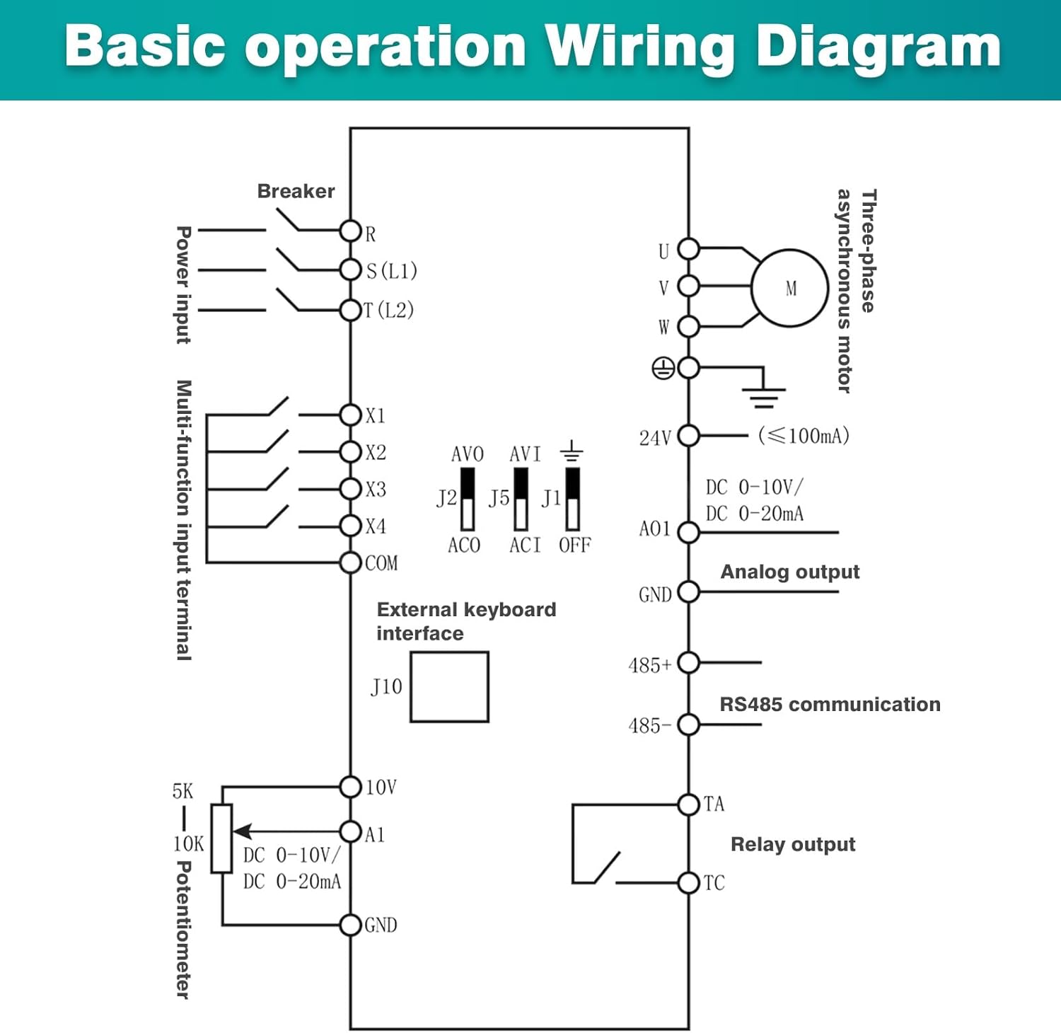
Figure 5.3: Comprehensive basic operation wiring diagram, detailing connections for power input (R, S, T), multi-function input terminals (X1-X4, COM), external keyboard interface, analog output (AO1, GND), RS485 communication (485+, 485-), relay output (TA, TC), and potentiometer (5K, 10K, A1, GND) for external control.
Terminal Connections:
- Input (L1, L2): Connect single-phase 220V AC power.
- Output (U, V, W): Connect to the three-phase motor terminals.
- Ground (GND): Connect to a reliable earth ground.
- Control Terminals (X1-X4, COM, A1, etc.): These are for external control signals such as start/stop, forward/reverse, analog speed reference (potentiometer), and communication. Refer to the detailed wiring diagram for specific functions.
6. Operating Instructions
6.1 Control Panel Overview
The VFD features a user-friendly control panel for monitoring and setting parameters.

Figure 6.1: The VFD's keyboard operation instructions, showing the layout of the status display area, numeric up/down keys, frequency setting knob, parameter data setting button (PRG), Run key, and Stop/Reset button (RST).
- Status Display Area: Shows current frequency, voltage, current, and operational status (FWD/REV, ALM).
- PRG (Program) Button: Enters/exits parameter setting mode.
- Up/Down Arrows: Used to navigate parameters or adjust values.
- ENTER Button: Confirms parameter selection or value changes.
- RUN Button: Starts motor operation.
- STOP/RST Button: Stops motor operation or resets alarms.
- Frequency Setting Knob: Adjusts the output frequency (and thus motor speed) in real-time.
6.2 Basic Operation
- Power On: After ensuring all wiring is correct and secure, apply single-phase 220V power to the VFD. The display will light up.
- Set Frequency: Use the frequency setting knob to set the desired output frequency. The display will show the set frequency.
- Start Motor: Press the RUN button. The motor will start accelerating to the set frequency.
- Stop Motor: Press the STOP/RST button. The motor will decelerate and stop.
- Reverse Direction: (If configured via control terminals X1-X4) Activate the appropriate control terminal to change motor direction. Refer to the detailed parameter manual for specific settings.
6.3 Parameter Setting
To access and modify advanced parameters:
- Press the PRG button to enter parameter setting mode. The display will show a parameter code (e.g., P00).
- Use the Up/Down arrow buttons to navigate through parameter groups and individual parameters.
- Press ENTER to select a parameter. The current value will be displayed.
- Use the Up/Down arrow buttons or the frequency setting knob to modify the value.
- Press ENTER again to save the new value.
- Press PRG to exit parameter setting mode.
Refer to the complete parameter list in the separate detailed manual for specific parameter functions and ranges.
7. Maintenance
Regular maintenance ensures the longevity and reliable operation of your VFD.
- Cleaning: Periodically clean the VFD's exterior and ventilation openings to prevent dust accumulation. Use a soft, dry cloth. Do not use liquid cleaners.
- Fan Inspection: Check the cooling fan for proper operation and ensure it is free from obstructions. Replace if noisy or not functioning correctly.
- Terminal Check: Periodically inspect all wiring terminals for tightness. Loose connections can cause overheating and malfunction.
- Environmental Conditions: Ensure the operating environment remains within specified temperature and humidity ranges.
WARNING: Always disconnect power and wait for at least 10 minutes before performing any maintenance to allow capacitors to discharge.
8. Troubleshooting
This section provides solutions to common issues. For problems not listed here, contact technical support.
| Problem | Possible Cause | Solution |
|---|---|---|
| VFD does not power on | No input power; Blown fuse; Incorrect wiring | Check power supply; Inspect fuses; Verify input wiring. |
| Motor does not start | RUN command not issued; Emergency stop active; Motor wiring error; Overload | Press RUN; Check emergency stop circuit; Verify motor wiring (U, V, W); Reduce load or check motor. |
| Motor runs in wrong direction | Incorrect phase sequence; Parameter setting for direction | Swap any two motor output phases (U, V, W); Adjust direction parameter (if applicable). |
| Overcurrent alarm (OC) | Motor overload; Short circuit in motor wiring; Rapid acceleration/deceleration | Reduce load; Check motor and wiring for shorts; Increase acceleration/deceleration time parameters. |
| Overvoltage alarm (OV) | Input voltage too high; Rapid deceleration with high inertia load | Check input voltage; Increase deceleration time; Consider adding a braking resistor if issue persists. |
| Undervoltage alarm (UV) | Input voltage too low; Power supply instability | Check input voltage; Ensure stable power supply. |
| Overheat alarm (OH) | Insufficient cooling; Ambient temperature too high; Fan malfunction | Ensure proper ventilation; Check ambient temperature; Inspect cooling fan. |
9. Applications
The DEWIN MS500-2S-2.2G VFD is versatile and suitable for a wide range of industrial and commercial applications requiring precise motor speed control. Examples include:

Figure 9.1: Examples of equipment where the VFD can be widely applied, including motors, water pumps, fans, blenders, air compressors, and conveyors.
- Fans and ventilation systems
- Water pumps and fluid transfer systems
- Oil pumping presses
- Compressors
- Conveyor belts
- Injection molding machines
- Crushers and mixers
- Ball mills and other general industrial equipment
10. Warranty and Support
For warranty information, please refer to the terms and conditions provided at the time of purchase or contact your vendor. For technical support, troubleshooting assistance beyond this manual, or spare parts inquiries, please contact DEWIN customer service or your authorized distributor.