1. Product Overview
The CUIPPWRJ F405 V3 BLS 60A 30x30 Flight Controller and 4in1 ESC Stack is designed for freestyle drones, offering an integrated solution for flight management and motor control. This stack delivers efficient power output for improved flight times and performance, featuring an intuitive setup process suitable for both beginners and experienced drone builders.
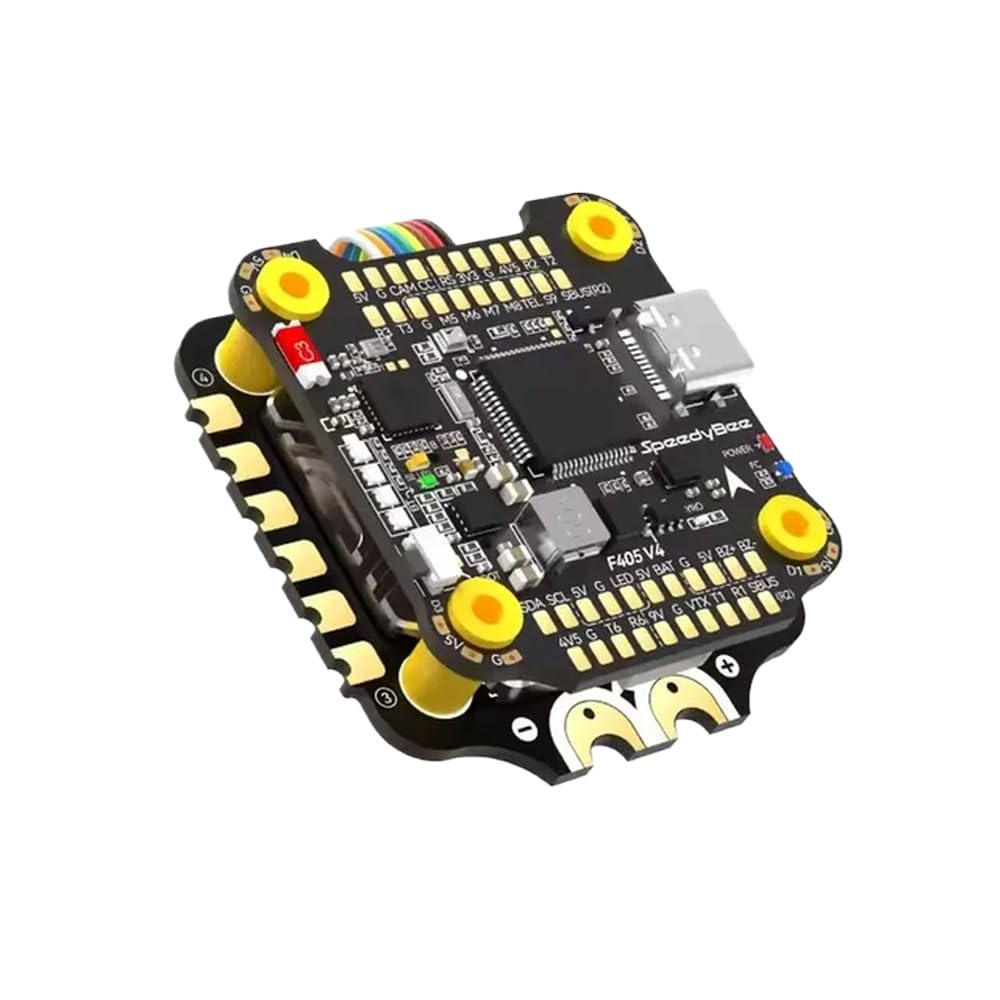
Figure 1: CUIPPWRJ F405 V3 BLS 60A 30x30 Flight Controller and 4in1 ESC Stack. This image displays the compact design of the integrated flight controller and electronic speed controller unit.
2. Key Features
- Versatile Design: Specifically engineered for freestyle drones, enhancing the DIY build experience.
- High Performance: Incorporates an F405 flight controller for responsive and efficient flight management.
- Integrated Solution: Combines a 60A 4in1 ESC for simplified installation and cleaner wiring.
- Broad Compatibility: Supports a wide range of motors and configurations, allowing for customized setups.
- Enhanced Durability: Constructed to withstand the demands of intensive freestyle flying.
3. Setup Guide
Follow these steps for proper installation and initial configuration of your flight controller and ESC stack.
3.1 Physical Installation
- Mounting: Securely mount the F405 V3 BLS 60A stack onto your drone frame using appropriate standoffs and screws. Ensure proper orientation as indicated by the arrow on the flight controller.
- Motor Connections: Solder the motor wires from your drone to the corresponding pads on the 4in1 ESC. Pay close attention to the motor numbering and rotation direction.
- Power Connection: Solder the main battery lead (XT60/XT30 connector) to the designated battery pads on the ESC. Double-check polarity (+ and -) to prevent damage.
3.2 Peripheral Wiring
Connect essential peripherals to the flight controller:
- Receiver (RX): Connect your radio receiver to the appropriate UART port on the flight controller (e.g., SBUS, CRSF, iBUS). Refer to the flight controller's pinout diagram.
- Video Transmitter (VTX): Connect the VTX to the designated VTX pads for video signal, ground, and power.
- Camera: Connect your FPV camera to the camera input pads on the flight controller or VTX.
- GPS (Optional): If using GPS, connect it to a free UART port.
3.3 Software Configuration
- Connect to PC: Connect the flight controller to your computer using a USB cable.
- Install Drivers: Ensure necessary drivers (e.g., STM32 Virtual COM Port Driver, Zadig) are installed.
- Flash Firmware: Open your preferred configurator software (e.g., Betaflight Configurator, INAV Configurator). Select the correct target for your F405 V3 flight controller and flash the latest stable firmware.
- Initial Setup: Follow the configurator's setup wizard to calibrate accelerometers, set up motor protocols (e.g., DShot600), configure your receiver, and assign flight modes.
- Motor Test: Carefully test motor direction and functionality within the configurator. Correct any reversed motors by re-soldering or using the ESC configurator.
4. Operating Instructions
This section outlines the basic steps for operating your drone with the CUIPPWRJ F405 V3 BLS 60A stack.
4.1 Pre-Flight Checks
- Inspect all wiring for loose connections or damage.
- Ensure propellers are securely attached and oriented correctly.
- Verify battery is fully charged and securely mounted.
- Check radio transmitter battery level and ensure it is powered on.
4.2 Powering On and Arming
- Power On: Connect the fully charged battery to the drone's main power lead. The flight controller will initialize, indicated by LED lights.
- Arming: With the drone on a stable, level surface and clear of obstacles, perform the arming sequence configured in your flight controller software (e.g., stick command, switch). The motors will spin slowly, indicating the drone is armed.
4.3 Flight
- Gently increase throttle to lift off.
- Use the pitch, roll, and yaw sticks on your transmitter to control the drone's movement.
- Monitor battery voltage and flight time.
4.4 Disarming
To safely disarm the drone, perform the disarming sequence configured in your flight controller software. The motors will stop spinning. Always disarm before approaching the drone or after landing.
5. Maintenance
Regular maintenance ensures the longevity and reliable performance of your CUIPPWRJ F405 V3 BLS 60A stack.
- Post-Flight Inspection: After each flight, visually inspect the flight controller and ESC for any signs of physical damage, loose wires, or debris.
- Cleaning: Gently clean the components with a soft brush or compressed air to remove dust, dirt, or grass. Avoid using liquids directly on the electronics.
- Firmware Updates: Periodically check for and install the latest stable firmware for your flight controller and ESC. Firmware updates often include performance improvements and bug fixes.
- Solder Joint Integrity: Occasionally inspect solder joints for cracks or cold joints, especially after hard crashes. Re-solder if necessary.
- Component Replacement: If any component on the stack is damaged beyond repair, replace it with an identical or compatible part.
6. Troubleshooting
This section addresses common issues you might encounter.
6.1 No Power to Flight Controller/ESC
- Check Battery: Ensure the battery is charged and properly connected.
- Inspect Power Leads: Verify that the main battery leads are securely soldered to the ESC and that there are no shorts.
- Fuse Check: Some setups may include a fuse; check if it's blown.
6.2 Motors Not Spinning or Spinning Incorrectly
- Arming State: Ensure the drone is armed.
- ESC Calibration: Verify ESCs are properly calibrated (if applicable to your ESC protocol).
- Motor Direction: Check motor direction in the configurator. Adjust if necessary.
- Wiring: Inspect motor wiring for loose connections or incorrect soldering.
- Motor Protocol: Ensure the correct motor protocol (e.g., DShot600) is selected in the configurator.
6.3 No Signal from Receiver
- Binding: Confirm your receiver is correctly bound to your radio transmitter.
- Wiring: Check the receiver's wiring to the flight controller for correct connections (signal, ground, power).
- UART Configuration: Verify the correct UART port is enabled for serial RX in the flight controller configurator.
- Receiver Protocol: Ensure the correct receiver protocol (e.g., SBUS, CRSF) is selected in the configurator.
6.4 Unstable Flight / Drifting
- Accelerometer Calibration: Recalibrate the accelerometer on a level surface.
- Vibrations: Check for excessive vibrations from motors or propellers. Balance propellers if needed.
- PID Tuning: Adjust PID (Proportional-Integral-Derivative) values in the configurator. Start with default settings and fine-tune gradually.
- Mounting: Ensure the flight controller is securely mounted and isolated from vibrations.
7. Product Specifications
| Feature | Detail |
|---|---|
| Model Number | CUIPPWRJ123 |
| Flight Controller | F405 V3 |
| ESC Current | 60A (4in1) |
| Stack Size | 30x30mm |
| Package Dimensions | 1.18 x 0.79 x 0.39 inches |
| Item Weight | 14.1 ounces |
| Manufacturer | CUIPPWRJ |
8. Warranty and Support
8.1 Warranty Information
This product is covered by a limited warranty against manufacturing defects. Please retain your proof of purchase for warranty claims. The warranty period and terms may vary by region. For specific warranty details, please refer to the official CUIPPWRJ website or contact customer support.
8.2 Customer Support
For technical assistance, troubleshooting, or any questions regarding your CUIPPWRJ F405 V3 BLS 60A 30x30 Flight Controller and 4in1 ESC Stack, please contact CUIPPWRJ customer support through their official website or the retailer from whom you purchased the product. Provide your model number (CUIPPWRJ123) and a detailed description of your issue for faster service.