1. Introduction
This manual provides essential information for the proper installation, operation, and maintenance of your CUIPPWRJ F405 V3 Flight Controller and BLS 50A 4-in-1 ESC. This integrated unit is designed for high-performance racing quadcopters, offering robust control and efficient power distribution. Please read this manual thoroughly before use to ensure safe and optimal performance.
Safety Precautions
- Always disconnect the battery before performing any installation, maintenance, or inspection.
- Ensure all connections are secure and correctly polarized to prevent damage to components.
- Avoid short circuits. Handle with care to prevent electrostatic discharge.
- Operate in a well-ventilated area.
- Seek professional assistance if you are unsure about any installation or configuration steps.
2. Specifications
Key technical specifications for the F405 V3 Flight Controller and BLS 50A 4-in-1 ESC unit:
| Feature | Detail |
|---|---|
| Flight Controller | F405 V3 |
| ESC Type | BLS 50A 4-in-1 |
| Mounting Pattern | 30x30mm |
| Dimensions | 1.18 x 0.79 x 0.39 inches (Package Dimensions) |
| Weight | 14.1 ounces (Item Weight) |
| Manufacturer | CUIPPWRJ |
| Model Number | CUIPPWRJ123 |
3. Setup and Installation
Proper installation is crucial for the performance and safety of your drone. Follow these guidelines carefully.
3.1 Physical Installation
- Mounting: The unit features a standard 30x30mm mounting pattern. Securely mount the flight controller and ESC stack to your drone frame using appropriate standoffs and screws. Ensure there is no contact with carbon fiber or other conductive materials that could cause a short circuit.
- Orientation: Pay attention to the arrow on the flight controller board, which indicates the forward direction of the drone. This is critical for correct flight stabilization.
3.2 Wiring Connections
Refer to the diagram below for typical wiring connections. Ensure all solder joints are clean and strong.
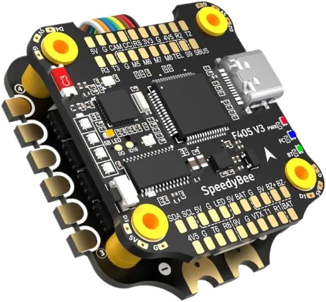
Figure 1: F405 V3 Flight Controller and BLS 50A 4-in-1 ESC Overview.
This image displays the integrated flight controller and 4-in-1 ESC unit. Key components and connection points are visible, including:
- Top Board (Flight Controller): Features the F405 V3 processor, USB-C port, and various pads for connections such as 5V, G (Ground), CAM (Camera), CC (Current Sensor), RS (Receiver Signal), 3V3, 4V5, R2, T2, R3, T3, M5-M8 (Motor outputs), TEL (Telemetry), S9 (SBUS), SB LED (Status LED), DO (Digital Output), IO10.
- Bottom Board (ESC): Integrated 50A 4-in-1 ESC.
- Power & Signal Pads: Clearly labeled pads for SDA, SCL, 5V, G, LED, 5V, BAT (Battery Voltage), G, 5V, BZ+BZ- (Buzzer), 4V5, G, T6, R6, 9V, G, VTX (Video Transmitter), T1, R1, BAT.
- LED Indicators: PWR (Power), FC (Flight Controller status), BT (Bluetooth, if applicable).
- Mounting Holes: Four yellow-ringed holes for 30x30mm mounting.
- Battery Connection: Connect your main flight battery (typically 3S-6S LiPo) to the designated BAT pads on the ESC. Ensure correct polarity.
- Motor Connections: Solder motor wires to the corresponding motor pads (M1-M4) on the ESC. Verify motor direction in software.
- Receiver Connection: Connect your receiver (e.g., SBUS, CRSF, PPM) to the appropriate UART pads (e.g., S9 for SBUS) on the flight controller.
- Video System: Connect your FPV camera to CAM and G pads, and your Video Transmitter (VTX) to VTX, G, and appropriate power pads (e.g., 9V or 5V).
- Other Peripherals: Connect GPS, Buzzer, LEDs, etc., to their respective pads as indicated in the diagram and the flight controller's pinout documentation.
3.3 Software Configuration
After physical installation, the flight controller requires software configuration. This typically involves connecting the unit to a computer via the USB-C port and using a configurator application.
- Firmware Flashing: It is recommended to flash the latest stable firmware (e.g., Betaflight, EmuFlight, INAV) compatible with the F405 V3 board.
- Initial Setup: Follow the configurator's setup wizard to calibrate accelerometers, configure receiver protocols, set up motor outputs, and define flight modes.
- ESC Protocol: Configure the ESC protocol (e.g., DShot600) in the flight controller software to match the capabilities of the BLS 50A ESC.
- PID Tuning: Adjust PID (Proportional-Integral-Derivative) values for optimal flight performance. This is an advanced step and may require iterative testing.
4. Operating Instructions
Once installed and configured, your drone is ready for operation. Always perform pre-flight checks.
- Pre-Flight Checks:
- Verify battery voltage and secure connection.
- Check propeller tightness and orientation.
- Confirm radio control link and arming switch functionality.
- Ensure no loose wires or debris are present.
- Arming: Arm the drone using the configured switch on your radio transmitter. Motors will spin at idle speed.
- Flight: Operate the drone using your radio transmitter. Start with gentle movements to assess stability and control.
- Disarming: Disarm the drone using the configured switch to stop the motors. Always disarm before approaching the drone.
5. Maintenance
Regular maintenance helps ensure the longevity and reliability of your flight controller and ESC.
- Cleaning: Periodically inspect the board for dust, dirt, or debris. Use a soft brush or compressed air to gently clean the components. Avoid using liquids.
- Connection Inspection: Regularly check all solder joints and connectors for signs of fatigue, corrosion, or loosenness. Re-solder or replace as necessary.
- Firmware Updates: Check the manufacturer's website or flight controller firmware project pages for new firmware releases. Updating firmware can provide performance improvements, new features, and bug fixes. Follow official instructions carefully during the update process.
- Physical Damage: After any crash or hard landing, inspect the board for cracks, bent pins, or damaged components. Replace damaged parts immediately.
6. Troubleshooting
This section addresses common issues you might encounter.
- No Power / No LED Indicators:
- Check battery connection and voltage.
- Inspect for short circuits on the board or connected components.
- Verify USB cable connection if powering via USB.
- Motors Not Spinning / Incorrect Direction:
- Ensure the drone is armed.
- Check motor wiring to the ESC.
- Verify ESC protocol and motor mapping in flight controller software.
- Calibrate ESCs if necessary (refer to ESC specific instructions).
- Adjust motor direction in the configurator or by swapping two motor wires.
- No Receiver Input:
- Confirm receiver is powered and bound to the transmitter.
- Check receiver wiring to the flight controller (signal, ground, power).
- Verify UART configuration and receiver protocol in flight controller software.
- Unstable Flight / Drifting:
- Recalibrate accelerometer.
- Check propeller balance and condition.
- Review PID tuning settings.
- Ensure flight controller is securely mounted and isolated from vibrations.
7. Support
For further assistance, please refer to the manufacturer's official website or contact their customer support. Online communities and forums dedicated to FPV drones can also be valuable resources for troubleshooting and advanced configuration.