
1. Introduction
The Yahboom ROS Robot Kit Sunburst RDK X5 Standard Edition is an educational robotic platform designed for learning and development in robotics. It is based on the RDK X3/X5 development board, offering sufficient computing resources for real-time data processing and complex computing tasks. This kit supports Python programming and the ROS2 operating system, enabling users to develop various intelligent algorithms and explore advanced robotic applications.
Key functionalities include visual line patrol, image classification, target inspection, and radar mapping navigation. The robot can be controlled via a mobile phone application, PS2 handle, computer keyboard, or directly through the ROS operating system. Its robust all-aluminum alloy chassis, combined with Mecanum wheel four-wheel independent drive, provides strong maneuverability and flexibility, making it suitable for indoor development and research. Yahboom provides comprehensive tutorials covering OpenCV image processing, multi-platform robot control, and robot kinematics analysis.
2. What's in the Box (Packing List)
Please verify that all components listed below are included in your package. If any items are missing or damaged, please contact customer support.
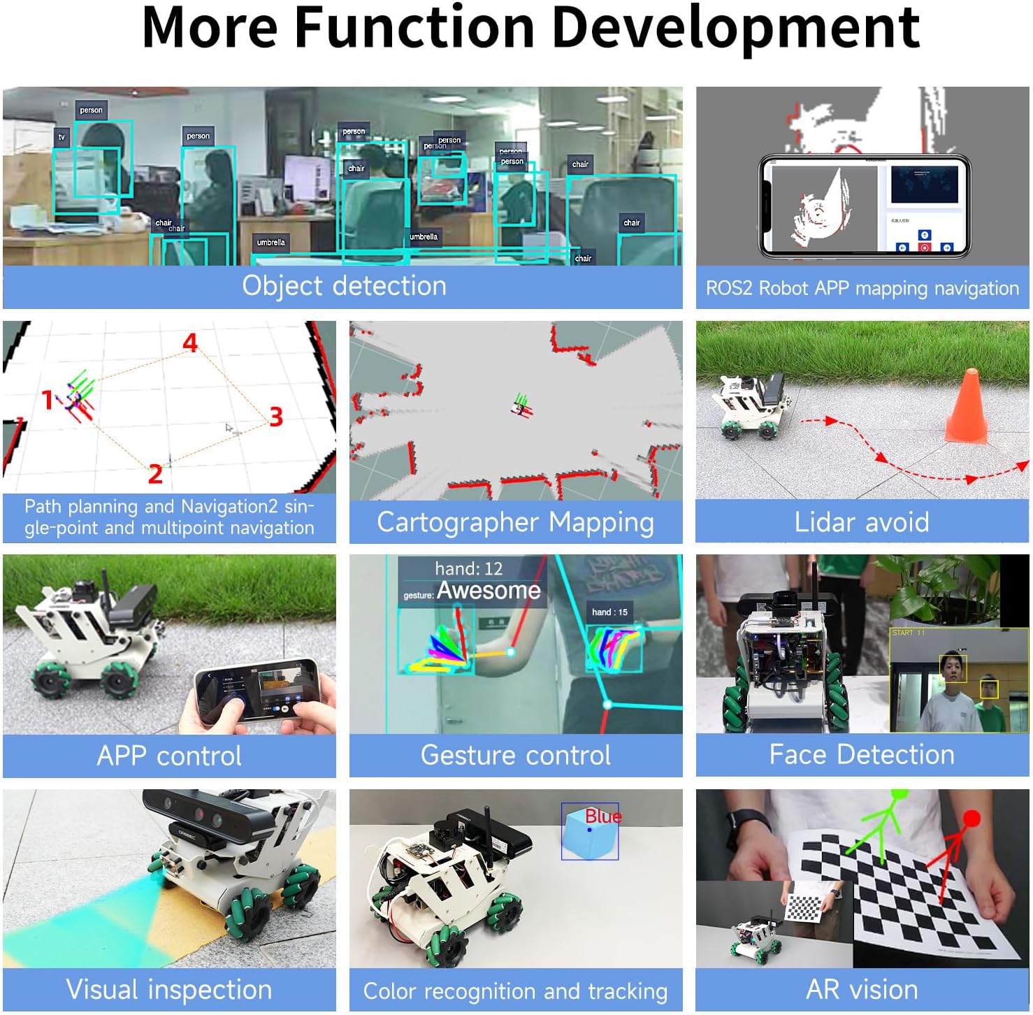
Image: Detailed view of the Yahboom ROS Robot Kit packing list, showing all included components.
- RDK Robot aluminum alloy parts *5
- 65mm Mecanum wheel *4
- RGB cooling HAT *1
- USB HUB expansion board *1
- OLED screen *1
- IMX219 MIPI camera *1
- 8.4V2A power charger *1
- M200 Lidar *1
- USB wireless handle *1
- 64GB TF card *1
- Several screws and copper columns
- RDK robot acrylic plate *1
- ROS robot expansion board *1
- 310 encoder reduction motor *4
- OLED screen acrylic protective board *1
- Antenna *1
- Instructions manual *1
- 6600mAh 7.4V battery pack *1
- Screwdriver *1
- Card reader *1
- Several wires
- Astra Pro Plus depth camera (including bracket) (optional)
- RDK X3 development board (including serial port module) (optional)
- RDK X5 development board (optional)
3. Product Structure and Components
The Yahboom ROS Robot Kit features a modular design, allowing for easy assembly and understanding of its various components. Below is an exploded view illustrating the main parts of the robot.

Image: Exploded diagram of the robot, detailing the placement of components such as the MS200 lidar, OLED display, RDK X3/X5 board, and Mecanum wheels.
Key Components:
- MS200 Lidar: For environmental scanning and obstacle avoidance.
- OLED Display: Provides real-time status information.
- RDK X3/X5 Board: The central processing unit for the robot's operations.
- RGB Cooling HAT: Ensures optimal temperature for the development board.
- 65mm Mecanum Wheels: Enable omnidirectional movement.
- 7.4V Battery Pack: Powers the robot.
- Astra Pro Plus Depth Camera (Optional): For advanced visual perception and 3D mapping.
- ROS Robot Expansion Board: Connects various sensors and actuators.
- USB HUB Expansion Board: Provides additional USB interfaces.
- MIPI Camera: For standard visual input.
- 310 Encoder Geared Motor: Provides precise movement control.
4. Setup and Assembly
Assembly of the Yahboom ROS Robot Kit involves connecting the various mechanical and electronic components. Refer to the detailed assembly guide provided in the package for step-by-step instructions. Ensure all connections are secure before powering on the device.
General Assembly Steps:
- Unpack all components and verify against the packing list.
- Assemble the aluminum alloy chassis according to the provided diagrams.
- Mount the 310 encoder geared motors and Mecanum wheels.
- Install the RDK X3/X5 development board, ROS robot expansion board, and USB HUB expansion board.
- Connect the MS200 Lidar, MIPI camera, and optional Astra Pro Plus depth camera.
- Install the RGB cooling HAT and OLED display.
- Connect all necessary wiring, ensuring correct polarity and secure connections.
- Insert the 7.4V battery pack and connect it to the power input.
For detailed visual instructions, please consult the official Yahboom assembly videos or documentation.
5. Operating Instructions
5.1 Product Functions Overview
The robot kit supports a wide range of functions across various modules:

Image: Infographic detailing the functional capabilities of the robot kit, categorized by Lidar, Depth Camera, ROS Master, MIPI Camera, OpenCV, and Robot Course.
Lidar Functions:
- Introduction and use of lidar
- Lidar obstacle avoidance
- Lidar tracking
- Lidar guard
- Patrol
- Gmapping mapping
- Cartographer mapping
- Navigation and avoiding
- APP mapping and navigation
Depth Camera Functions:
- Depth camera usage
- Camera internal reference
- AR vision
- Color tracking
- KCF object tracking
ROS Master (RDK X3/X5) Functions:
- ROS2 Introduction
- ROS2 common commands and tools
- ROS2 topic communication
- ROS2 service communication
- ROS Launch file
MIPI Camera Functions:
- Camera drive
- Color HSV value adjustment
- Color recognition
- Color tracking
- Color follow
- QR code recognition
- Face detection
- Object detection
- Visual line patrol-OpenCV
- Visual line patrol-Deep Learning
- Human tracking
- Gesture control
OpenCV Functions:
- Getting Started with OpenCV
- OpenCV Geometric transformation
- OpenCV image processing
- OpenCV image beautification
- QR code creation and recognition
Robot Course Functions:
- PID algorithm theory
- Robot information release
- Robot control
- Robot state estimation
- Robot calibration
- Robot trajectory tracking
- URDF model
5.2 ROS2 System Overview
The kit utilizes ROS2, the successor to ROS, which is a powerful and flexible operating system for robots. ROS2 addresses communication challenges between various robot components and integrates advanced algorithms.

Image: Diagram illustrating the evolution from ROS1 to ROS2, and the use of ROS2 Foxy and Humble versions with RDK X3 and RDK X5 robots respectively.
Yahboom employs the Foxy version with strong stability and rich information, and provides exclusive functions adapted to ROS2, ensuring compatibility and robust performance.
5.3 Advanced Function Development
The robot supports various advanced functions for complex tasks:

Image: Grid of advanced functions including object detection, ROS2 APP mapping navigation, path planning, Cartographer mapping, Lidar avoidance, APP control, gesture control, face detection, visual inspection, color recognition, and AR vision.
Lidar Capabilities:

Image: Visual representation of Lidar functions such as obstacle avoidance, following, guarding, patrolling, and various mapping and navigation techniques.
- Lidar Avoid: Detects the surrounding environment in real-time and autonomously avoids obstacles.
- Lidar Following: Enables the robot to follow a target closest to the radar.
- Lidar Guard: Targets within a defined lidar range will be locked on, and the vehicle will face the closest target.
- Lidar Patrol: The robot follows a path defined by ROS dynamic parameter adjustment tools.
- Path Planning and Navigation: Realizes single-point and multi-point navigation by setting target points.
- Gmapping Mapping: Builds indoor maps in real-time with minimal computation.
- Cartographer Mapping: Utilizes a 2D and 3D SLAM library for comprehensive mapping.
MIPI Camera Capabilities:

Image: Examples of MIPI camera functions including object detection, body following, gesture control, visual inspection, face detection, color recognition and tracking, and QR code recognition.
- Object Detection: Supports detection of 80 types of objects including people, animals, fruits, and vehicles.
- Body Following: Controls the robot to move with a human body, identifying key points like head, face, and hand frames.
- Gesture Control: The robot can be controlled by gestures, including left/right rotation and forward/backward translation.
- Visual Inspection: Visual line inspection using OpenCV color line inspection and deep learning.
- Face Detection: Uses Haar face feature to detect faces in real-time and limit the position information.
- Color Recognition and Tracking: Analyzes HSV values to identify and track selected colors.
- QR Code Recognition and Control: Analyzes QR code data to execute predetermined instructions.
Depth Camera Capabilities:

Image: Demonstrations of depth camera functions including RTAB 3D mapping, deep color tracking, AR vision, KCF object tracking, multi-vehicle navigation, and multi-vehicle synchronous remote control.
- RTAB 3D Mapping and Navigation: Integrates vision and radar for global relocation and autonomous positioning.
- Deep Color Tracking: Uses depth information to maintain a safe distance from tracked objects.
- AR Vision: Supports various AR images, presenting augmented reality content on a checkerboard paper.
- KCF Object Tracking: Image-based correlation KCF algorithm for selecting and following targets.
- Multi-vehicle Navigation: Enables coordinated movement of multiple robots.
- Multi-vehicle Synchronous Remote Control: Allows simultaneous control of multiple robots.
5.4 Control Methods
The robot offers multiple control interfaces for flexibility:

Image: Overview of control methods including APP control, rocker control (PS2 handle), keyboard control, trajectory tracking, linear/angular velocity calibration, and robot pose estimation.
- APP Control: Supports iOS/Android dual system for remote control, including movement and parameter adjustment.
- Rocker Control (PS2 Handle): Controls robot movement (forward, backward, turn left, turn right).
- Keyboard Control: Uses a computer keyboard for directional control.
- Trajectory Tracking: The robot can run according to a given trajectory, with visualization on a virtual machine.
- Linear/Angular Velocity Calibration: Parameters can be adjusted dynamically for precise velocity control.
- Robot Pose Estimation: Reads IMU data and speed data, outputting Odometry data fused from IMU and Odometry.
5.5 Cross-platform Interconnection Control
The robot supports various cross-platform control and programming methods:

Image: Visuals demonstrating remote control APP, mapping and navigation APP, real handle control, computer keyboard control, Jupyter Lab programming control, and ROS system control.
- Remote Control APP: Supports iOS/Android for basic robot control.
- Mapping and Navigation APP: Supports iOS/Android, ROS1/ROS2 for advanced navigation.
- Real Handle Control: Physical game controller for intuitive movement.
- Computer Keyboard Control: Direct control from a computer.
- Jupyter Lab Programming Control: For developing and executing Python code.
- ROS System Control: Full integration with the ROS ecosystem for advanced robotics development.
6. Technical Specifications
6.1 Development Board Comparison
The RDK X3/X5 development boards offer competitive performance compared to other popular single-board computers:

Image: Comparison table of RDK X3 2.0, RDK X5, Raspberry Pi 5, and JETSON NANO B01 development boards, detailing CPU, computing power, RAM, graphics acceleration, and other features.
| Development board | RDK X3 2.0 | RDK X5 | Raspberry Pi 5 | JETSON NANO B01 | |
|---|---|---|---|---|---|
| Hardware | CPU | 4-core A53 | 8-core A55 | 4-core A76 | 4-core A57 |
| Equivalent computing power | 5TOPS(INT8) | 10TOPS | / | 0.5TOPS(FP16) | |
| RAM | 2GB/4GB | 4GB/8GB | 2GB/4GB/8GB | 2GB/4GB | |
| Graphics acceleration | BPU | BPU/GPU | / | CUDA | |
| Coding/decoding | 4K@60fps | 4K@60fps | 4K@60fps | 4K@30fps | |
| Peripheral interface | USB/ETH/CSI/HDMI/3.5mm Headphone jack | USB/ETH/CSI/HDMI/3.5mm Headphone jack | USB/ETH/CSI/HDMI | USB/ETH/CSI/HDMI | |
| Software | Power | Max 15W | Max 25W | Max 25.5W | Max 20W |
| System | Ubuntu 20.04/22.04 | Ubuntu 22.04 | Ubuntu 22.04 | Ubuntu 18.04 | |
| Tool | apt installation | ||||
| Robot development framework | TogetherROS, ROS2 | TogetherROS, ROS2 | ROS | ROS, Isaac SDK | |
| Other | Deep learning framework | OpenExplore | OpenExplore | / | JetPack SDK |
| Origin place | China | China | U.K. | U.S. | |
| Application | Robot development | AI vision development, intelligent computing and robotics applications | Microcomputer board (multimedia, AI, development) | Comprehensive AI development platform |
6.2 RDK Main Control Board Interfaces
The RDK X3 and RDK X5 boards provide a rich set of interfaces for various peripherals and expansions.

Image: Detailed diagrams of the RDK X3 and RDK X5 main control boards, highlighting and labeling all input/output interfaces and their functions.
RDK X3 Board Interfaces:
- TF card interface (back)
- Type-C power interface
- Antenna interface
- MIPI CSI interface
- Debug UART
- Micro USB interface
- USB2.0 Type A interface x2
- HDMI interface
- Power LED indicator light
- 40PIN interface
- Ethernet interface
- USB 3.0 Type A interface
RDK X5 Board Interfaces:
- 3.5mm Headphone jack
- Power switch button
- Type-C Power interface
- RTC clock
- Type-C Device interface
- Debug serial port
- MIPI CSI interface *2
- PoE power supply interface
- Ethernet interface
- HDMI interface
- 40PIN interface
- 8/4GB RAM
- CAN FD high-speed interface
- USB3.0 *4
6.3 MS200 TOF Lidar (Standard)
The MS200 TOF Lidar is a standard component for environmental perception.

Image: Detailed specifications and an image of the MS200 TOF Lidar.
| Name | Parameter | Description |
|---|---|---|
| Principle of distance measurement | TOF | |
| Range | 0.03m-12.0m (90% reflectivity) | |
| Measurement accuracy | Typical value: ±10mm (0.2m - 2.0m) ±20mm (2.0m-12.0m) | In the normal room, under the condition of 90% reflectivity, the radar collects data statistical results at least 100 times. The accuracy is the difference between the data mean and the true value, and the precision is the sample standard deviation of the data. |
| Maximum value: ±15mm (0.2m-2.0m) ±30mm (2.0m-12.0m) | ||
| Data information | distance, angle, intensity, timestamp | |
| Anti-ambient light performance | 30,000Lux | |
| Dot frequency | 4,500 points/second | |
| Scanning frequency | 7-15HZ, default 10Hz | |
| Angular resolution | 0.8°@10Hz (single resolution and dot frequency related) | |
| Spinning speed | 7-15HZ, default 10Hz (configurable, 1Hz interval) | |
| Scan angle | 360° | |
| Eye Safety Level | Class 1 IEC60825-1:2014 | |
| Operating temperature | -10°C ~ 50°C (Typical value 25°C) | |
| Working power | DC 5.0±0.5V | |
| Storage temperature | -30°C ~ 70°C (Typical value 25°C) | |
| Product Size | 37.7*37.5*31.0 (length * width * height (unit: mm)) | |
| Net weight | about 40g | |
| Certified | RoHS2.0, REACH, CE, FCC | |
| Degree of protection | IP5X |
6.4 Astra Pro Plus Depth Camera (Optional)
The optional Astra Pro Plus depth camera enhances the robot's visual perception capabilities.

Image: Detailed specifications and an image of the Astra Pro Plus depth camera, highlighting its manual adjustment support.
| Name | Parameter | Description |
|---|---|---|
| 3D technology | ORBBECR monocular structured light | |
| Working range | 0.6-8m | |
| Accuracy (Depth) | 1cm ±3mm | |
| Field of View (FOV) (depth) | H 58.4° x V 45.8° | |
| Resolution @ frame rate (depth) | 640x480@30FPS | |
| 320x240@30FPS | ||
| 160x120@30FPS | ||
| Resolution @ frame rate (RGB) | 1920x1080@30FPS | |
| 1280x720@30FPS | ||
| 640x480@30FPS | ||
| Deep processing chip | MX6001 | |
| Close protection | support | |
| Field of view (RGB) | H66.1° V40.2° | |
| UVC (RGB) | support | |
| Supported operating systems | Android / Linux / Windows | |
| Data interface | USB2.0 | |
| Size(mm) | 164.85 * 48.25 * 40 | |
| Microphone | two-channel stereo | |
| Power consumption | <2.5W | |
| Safety | Class 1 laser | |
| Operating temperature | 10°C - 40°C |
6.5 RDK MIPI Camera (Standard)
The RDK MIPI camera is a standard vision component for the robot.

Image: Specifications and an image of the RDK MIPI camera, featuring the Sony IMX219 chip.
| Name | Parameter |
|---|---|
| Photosensitive chip | Sony IMX219 |
| Resolution | 8MP(3280x2464) |
| CMOS size | 1/4 inch |
| Aperture | 2.0 |
| Focal length | 2.96mm |
| Field of view | 77° |
| Distortion | <1% |
| Size | 25x24mm |
6.6 310 Geared Motor with Encoder
The robot uses 310 geared motors with encoders for precise and controlled movement.

Image: Specifications and an image of the 310 geared motor with encoder.
| Name | Parameter |
|---|---|
| Motor model | MD310Z0.74V |
| Rated voltage | 7.4V |
| Motor type | permanent magnet with brush |
| Output shaft | Diameter 3mm D type eccentric shaft |
| Gear set | 1:20 reduction ratio |
| Rated torque | 0.4kg.cm |
| Speed before deceleration | 9000rpm |
| Speed after deceleration | 450±10rpm |
| Rated power | 4.8W |
| Stall current | ±1.4A |
| Rated current | ±0.65A |
| Stall torque | ≥1.0kg.cm |
| Encoder type | AB phase incremental hall encoder |
| Encoder supply voltage | 3.3-5V |
| Number of magnetic loops | 13 line |
| Interface type | PH2.0 6pin |
| Function | With its own pull-up shaping, the micro-controller can directly read the signal pulse |
| Single motor weight | About 70g |
6.7 ROS Robot Expansion Board
The ROS robot expansion board is specifically designed for the ROS car, enabling control of various chassis types and providing power and IMU data.

Image: Diagram of the ROS robot expansion board, showing its various interfaces and components.
It can drive and control the robot chassis such as Mecanum wheel, Ackerman, 4-wheel differential, 2-wheel differential, omni-directional wheel, and crawler. The ROS master control can be controlled through the micro USB serial port and CAN bus interface. The expansion board receives 5V and 12V power inputs to supply power to the ROS controller. On-board 9-axis IMU can obtain the robot attitude information in real time. It has 5V/7.4V PWM servo and serial bus servo drive interface, suitable for various robotic arms. The driver code and hardware schematic diagram are open source.
6.8 USB HUB Expansion Board
The USB3.0 HUB expansion board addresses the issue of insufficient USB interfaces and power supply on the motherboard, supporting high-speed data transmission.

Image: Diagram of the USB HUB expansion board, showing its 4-channel USB3.0 ports and power inputs.
It expands 4 USB3.0 interfaces to ensure high-speed data transmission. It supports ROS Robot/Car, RDK-X3/Raspberry Pi/Jetson series boards, requiring no driver, plug and play.
6.9 Product Size Parameters
The physical dimensions of the assembled robot are as follows:

Image: Technical drawing showing the dimensions of the robot in millimeters.
| Parameter | RDK X3 | RDK X5 |
|---|---|---|
| Master control | ARM® Cortex® A53, 4xCore, 1.2GHz | ARMR CortexR A55, 8xCore, 1.5GHz |
| CPU | ARM® Cortex® A53, 4xCore, 1.2GHz | ARMR CortexR A55, 8xCore, 1.5GHz |
| Equivalent computing power | 5Tops | 10Tops |
| Operating system | Ubuntu20.04 + ROS2-Foxy | Ubuntu22.04 + ROS2 humble |
| RAM | 4GB | 8GB |
| Enter | MS200 lidar, CSI camera, wireless handle, depth camera (optional) | |
| Output | Motor, OLED, Buzzer | |
| Power supply | DC7.4V | |
| Battery life | 3.5H | |
| Remote control method | Handle control, keyboard control, APP control | |
| Communication method | WiFi network (LAN/AP) | |
| Vehicle body material | Aluminum alloy | |
| Safety protection | Anti connection protection, short circuit protection, locked rotor protection | |
| Product Size | 236.11*181.10*184.9mm | |
| Weight after assembly | Weight 1.93kg | |
7. Troubleshooting
If you encounter any issues during assembly or operation, please refer to the following general troubleshooting steps:
- Power Issues: Ensure the battery is fully charged and correctly connected. Check all power cables for secure connections.
- Connection Problems: Verify all sensor and motor connections to the expansion boards and main control board. Ensure Wi-Fi connectivity is stable for remote control.
- Software Errors: Confirm that the correct ROS2 system image is installed and all necessary drivers and libraries are up to date. Refer to the course catalog for software-related guidance.
- Movement Issues: Check motor connections and ensure Mecanum wheels are free from obstructions. Calibrate linear and angular velocities if movement is erratic.
- Sensor Malfunctions: Inspect lidar, camera, and depth camera connections. Ensure lenses are clean and free from obstructions.
For specific error codes or persistent problems, consult the detailed online documentation or contact Yahboom technical support.
8. Maintenance
Proper maintenance will ensure the longevity and optimal performance of your Yahboom ROS Robot Kit:
- Cleaning: Regularly clean the robot's chassis and components with a soft, dry cloth. Avoid using liquids or abrasive cleaners. Pay special attention to sensor lenses (camera, lidar) to ensure clear vision.
- Storage: When not in use for extended periods, store the robot in a cool, dry place away from direct sunlight and extreme temperatures. Disconnect the battery to prevent over-discharge.
- Battery Care: Follow battery charging guidelines. Do not overcharge or completely drain the battery. Store batteries at a partial charge (around 50%) if storing for long durations.
- Software Updates: Periodically check for software and firmware updates from Yahboom to ensure you have the latest features and bug fixes.
- Component Inspection: Periodically inspect all wires, connectors, and mechanical parts for wear or damage. Tighten any loose screws.
9. Warranty and Support
Yahboom provides technical support and warranty services for its products. For detailed warranty information, including coverage period and terms, please refer to the warranty card included in your package or visit the official Yahboom website.
Technical Support:
If you require assistance with assembly, programming, or troubleshooting, Yahboom offers online professional technical support. You can typically find support resources, FAQs, and contact information on the official Yahboom website. Please have your product model and purchase details ready when contacting support.
The kit also includes a comprehensive course catalog to guide users through various aspects of robotics development:
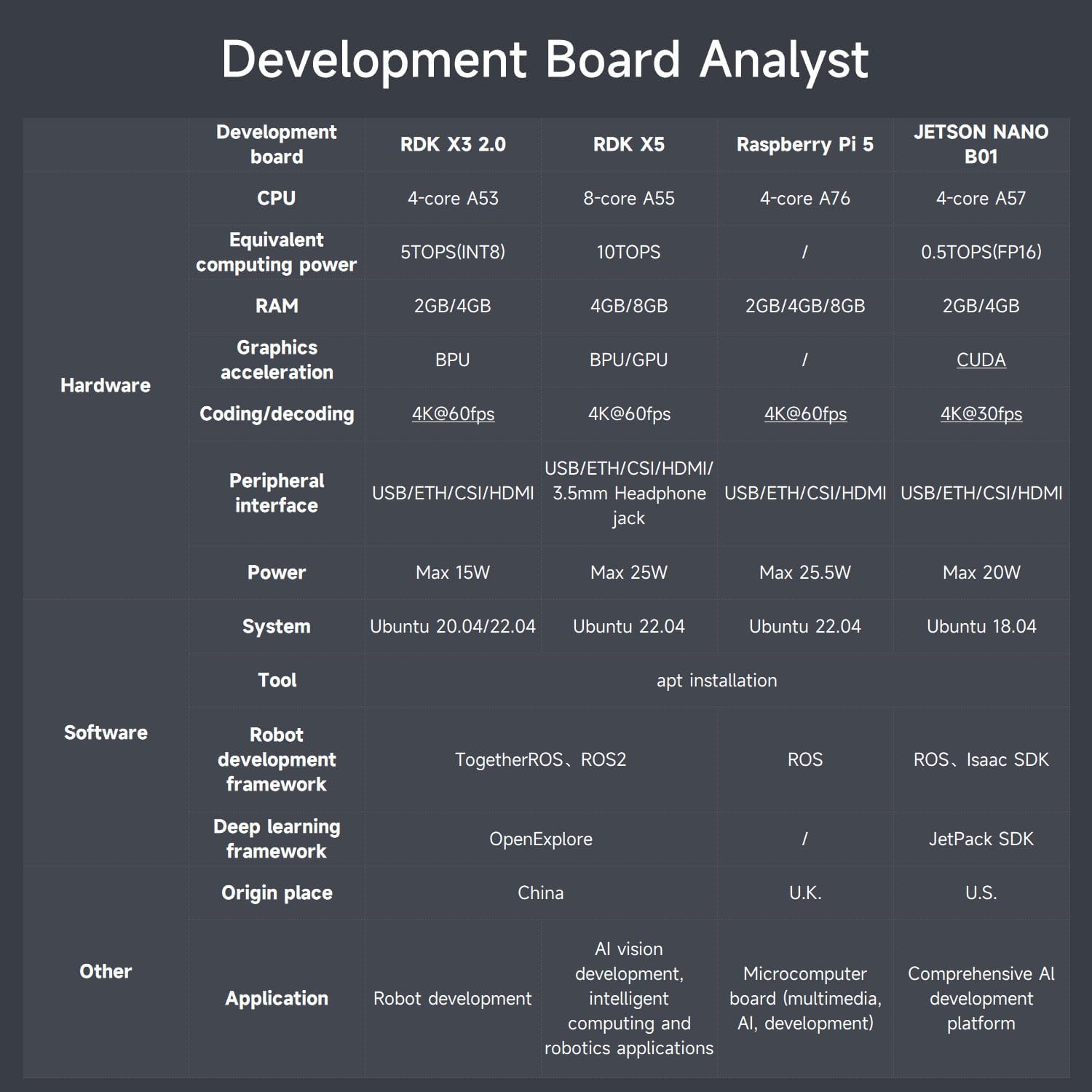
Image: Overview of the course catalog, listing topics such as basic setup, operating system, ROS2 basics, hardware, depth camera, OpenCV, MIPI camera, and robot control courses.


