1. Introduction
This manual provides essential information for the installation, operation, and maintenance of the QRLVJFMTY Fuel Shutoff Solenoid. This component is designed as a direct replacement for various Yanmar diesel engines and Thermo King units, ensuring reliable fuel flow control.
Compatibility: This solenoid is compatible with Yanmar Diesel Engines including 366, 3.66, 3,66, 395, 3.95, 3,95, 374, 3.74, 3,74 (3TNE72 series), 388, 3.88, 3,88 (3TNA72 series), 482, 4.82, 4,82 (4TNE84 series), and 486, 4.86, 4,86 (4TNE88 series). It replaces part numbers TK 41-6383, TK416383, 416383, and 41-4306.
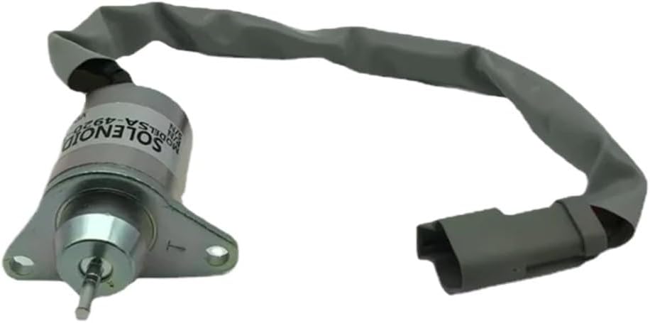
Figure 1: Front view of the QRLVJFMTY Fuel Shutoff Solenoid with its integrated wiring harness.
2. Product Features
- Quick Response: Designed for rapid action upon signal reception, ensuring efficient fuel control.
- Low Power Consumption: Operates with minimal energy, contributing to energy efficiency.
- Compact Structure: Small footprint allows for easy installation and integration into existing systems.
- Low Working Noise: Engineered to produce minimal operational noise.
- High Safety Performance: Constructed to ensure safe and reliable operation.
3. Safety Information
WARNING: Always disconnect the vehicle's battery before performing any installation or maintenance to prevent electrical shock or damage to the system.
- Ensure the engine is completely off and cooled down before beginning work.
- Wear appropriate personal protective equipment (PPE), including safety glasses and gloves.
- Handle fuel lines with care to prevent spills and exposure. Fuel is flammable.
- Refer to the engine manufacturer's service manual for specific procedures and torque specifications.
- If you are unsure about any step, seek assistance from a qualified technician.
4. Installation
The following steps provide a general guide for installing the fuel shutoff solenoid. Specific procedures may vary depending on the engine model. Always consult your engine's service manual.
- Preparation: Disconnect the negative terminal of the battery. Ensure the engine is cool.
- Locate Old Solenoid: Identify the existing fuel shutoff solenoid on your engine. It is typically located near the fuel injection pump or fuel filter housing.
- Disconnect Wiring: Carefully disconnect the electrical connector from the old solenoid. Note the orientation of the wiring if not clearly marked.
- Remove Old Solenoid: Unscrew any mounting bolts or nuts securing the old solenoid. Remove the solenoid from its mounting bracket or housing. Be prepared for a small amount of fuel leakage.
- Inspect Mounting Area: Clean the mounting surface to ensure a proper seal for the new solenoid.
- Install New Solenoid: Position the new QRLVJFMTY Fuel Shutoff Solenoid in the same location as the old one. Secure it with the appropriate mounting hardware. Do not overtighten.
- Connect Wiring: Reconnect the electrical connector to the new solenoid. Ensure a secure and proper connection.
- Final Checks: Reconnect the battery. Inspect all connections for tightness and ensure no tools or debris are left in the engine compartment.
- Test Operation: Start the engine and check for proper operation of the fuel shutoff solenoid. Listen for the solenoid's click when the ignition is turned on and off. Check for any fuel leaks.

Figure 2: Side view of the solenoid, highlighting the mounting flange and electrical connector for installation reference.
5. Operation
The fuel shutoff solenoid is an electrically operated valve that controls the flow of fuel to the engine's injection system. Its primary function is to cut off the fuel supply when the engine is turned off, preventing run-on and ensuring a clean shutdown.
- When the ignition key is turned to the "ON" position, the solenoid receives electrical power, which energizes an electromagnet.
- This electromagnet pulls a plunger, opening the fuel passage and allowing fuel to flow to the engine.
- When the ignition key is turned to the "OFF" position, power to the solenoid is cut.
- A spring then pushes the plunger back, closing the fuel passage and stopping the engine.
Proper operation is indicated by the engine starting and stopping correctly with the ignition key.
6. Maintenance
The QRLVJFMTY Fuel Shutoff Solenoid is designed for durability and requires minimal maintenance. However, periodic inspection can help ensure its longevity and reliable performance.
- Visual Inspection: Periodically check the solenoid and its wiring for any signs of damage, corrosion, or loose connections.
- Cleanliness: Keep the area around the solenoid clean and free from dirt, debris, and fuel residue.
- Connection Integrity: Ensure the electrical connector is securely attached and free from moisture or corrosion. Clean terminals if necessary.
- Functionality Check: If experiencing engine starting or stopping issues, test the solenoid's function by listening for the "click" when power is applied and removed.
7. Troubleshooting
| Problem | Possible Cause | Solution |
|---|---|---|
| Engine will not start (no fuel flow) | Solenoid not receiving power; Solenoid stuck closed; Faulty wiring/connector. | Check electrical connections and fuses. Test for voltage at solenoid. Replace solenoid if faulty. |
| Engine will not shut off (run-on) | Solenoid stuck open; Solenoid receiving constant power; Faulty ignition switch. | Check for constant voltage at solenoid when ignition is off. Replace solenoid if faulty. Inspect ignition switch. |
| Intermittent engine operation | Loose electrical connection; Intermittent power supply; Solenoid failing. | Secure all electrical connections. Check for stable voltage supply. Consider replacing solenoid. |
If troubleshooting steps do not resolve the issue, consult a qualified mechanic or engine service professional.
8. Specifications
- Model Number: TK 41-6383 (Replaces 41-4306, TK416383, 416383)
- Brand: QRLVJFMTY
- Compatibility: Yanmar Diesel Engines (3TNE72, 3TNA72, 4TNE84, 4TNE88 series)
- Package Dimensions: 0.39 x 0.39 x 0.39 inches
- Item Weight: 1.76 ounces
- Manufacturer: Zeng19961021
- Batteries Required: No
9. Warranty and Support
This QRLVJFMTY product is manufactured to high-quality standards. For specific warranty information or technical support, please refer to the retailer or manufacturer's official website where the product was purchased. Keep your purchase receipt as proof of purchase.


