
CREWORKS MLMNX14DE
CREWORKS 550W Metal Lathe User Manual
Model: MLMNX14DE | Brand: CREWORKS
1. Introduction
This user manual provides essential information for the safe and efficient operation, maintenance, and troubleshooting of your CREWORKS 550W Metal Lathe. Please read this manual thoroughly before operating the machine to ensure proper usage and to prevent injury or damage.
Product Overview
The CREWORKS 550W Metal Lathe (Model MLMNX14DE) is a compact yet powerful machine designed for small to medium-sized metalworking projects. Its variable speed motor and precise controls make it suitable for a variety of tasks including threading, turning, and drilling. With a 180 mm swing over bed and a 350 mm distance between centers, it offers versatility for hobbyists and professionals alike.

Figure 1: CREWORKS 550W Metal Lathe and included accessories.
2. Safety Instructions
Always prioritize safety when operating machinery. Failure to follow these instructions may result in serious injury or damage to the equipment.
- Read the Manual: Before operation, thoroughly read and understand all instructions and warnings in this manual.
- Personal Protective Equipment (PPE): Always wear safety glasses or a face shield. Use hearing protection when operating the lathe. Avoid loose clothing, jewelry, and long hair that could get caught in moving parts.
- Work Area: Ensure your work area is clean, well-lit, and free from clutter. Keep children and unauthorized personnel away from the machine.
- Machine Stability: Securely mount the lathe to a sturdy workbench to prevent movement during operation.
- Power Disconnection: Always disconnect the power supply before performing any adjustments, maintenance, or when the machine is not in use.
- Proper Workpiece Securing: Ensure the workpiece is securely clamped in the chuck or between centers. An improperly secured workpiece can become a dangerous projectile.
- Tool Selection: Use only sharp, correctly ground cutting tools suitable for the material being machined.
- Speed Control: Always start with a lower speed and gradually increase it as needed. Do not change the direction of rotation while the spindle is moving at high speed.
- Chip Removal: Never remove chips or swarf with your bare hands while the machine is running. Use a brush or hook.
- Emergency Stop: Familiarize yourself with the location and operation of the emergency stop button.
3. Components Included
Your CREWORKS Metal Lathe package includes the following components:
- 1x Mini Lathe
- 5x Lathe Tools
- 2x Screwdrivers
- 5x Hex Keys
- 1x Tailstock
- 3x Keys (for chuck, etc.)
- 3x Chuck Jaws (likely referring to a set of internal/external jaws)
- 1x Chuck Key
- 1x Spare Fuse
- 1x Cutting Oil Bottle
- 9x Metal Change Gears
- 1x Instructions Manual (this document)
4. Setup
Follow these steps to set up your metal lathe for initial operation.
4.1 Unpacking and Placement
- Carefully remove the lathe and all accessories from the packaging.
- Place the lathe on a sturdy, level workbench. Ensure it is securely fastened to prevent movement during operation.
Video 1: Unboxing and initial setup of the CREWORKS Metal Lathe. This video demonstrates the careful removal of the lathe from its wooden crate and placement on a workbench.
4.2 Installing the Chuck Guard
- Locate the transparent chuck guard and its mounting hardware.
- Align the guard with the mounting holes near the chuck.
- Securely fasten the guard using the provided screws and screwdriver. This guard is essential for safety during operation.
Figure 2: The chuck guard, shown installed on the lathe, provides protection from chips and rotating parts.
4.3 Installing the Tool Post
- Place the 4-way tool post onto the compound rest.
- Secure it in place using the provided bolts and hex key. Ensure it is firmly tightened to prevent movement during cutting operations.
- Insert the desired cutting tool into one of the tool post slots and tighten the retaining screws.
Figure 3: The 4-way tool post, ready for tool insertion, allows for quick changes of cutting tools.
4.4 Installing Change Gears (if required for specific threading)
The lathe comes with a set of metal change gears for various threading operations. Refer to the threading chart on the machine for the correct gear configuration for your desired thread pitch.
- Open the gear cover on the left side of the headstock.
- Loosen the retaining nuts and remove the existing gears.
- Install the required gears according to the threading chart, ensuring they mesh correctly.
- Tighten all retaining nuts and close the gear cover.
Video 2: Installation of metal change gears. This segment demonstrates how to access the gear train and replace gears for different threading operations.
5. Operating Instructions
This section details the basic operation of your CREWORKS Metal Lathe.
5.1 Powering On and Speed Control
- Ensure the emergency stop button is disengaged (pulled out).
- Connect the lathe to a suitable power outlet (220V).
- Turn the main power switch to the "ON" position.
- Use the variable speed control knob to adjust the spindle RPM. The digital display will show the current speed.
- The forward/reverse switch (F/R) controls the direction of spindle rotation. Always ensure the spindle has come to a complete stop before changing direction.

Figure 4: The digital display provides real-time spindle speed, adjustable via the control knob.
Video 3: Demonstration of digital speed control and forward/reverse operation. This video shows how to adjust the spindle speed and change its rotation direction.
5.2 Chuck Operation
The 3-jaw chuck is used to securely hold cylindrical or hexagonal workpieces.
- Insert the chuck key into one of the chuck keyholes.
- Rotate the chuck key to open or close the jaws. Ensure the jaws are clean and free of debris.
- Insert the workpiece and tighten the jaws firmly using the chuck key. Always remove the chuck key before starting the lathe.
- For different workpiece sizes or types, you may need to reverse the chuck jaws (internal vs. external gripping).

Figure 5: The adaptable 3-jaw chuck, capable of holding various workpiece shapes and sizes. The diagram illustrates internal and external jaw clamping ranges.
5.3 Carriage and Compound Rest Controls
The lathe features precise controls for movement along the X and Z axes.
- Carriage Handwheel: Moves the entire carriage assembly along the bed (Z-axis).
- Cross Slide Handwheel: Moves the cross slide perpendicular to the bed (X-axis).
- Compound Rest Handwheel: Allows for angled cuts and fine adjustments. It can be rotated to various angles.
- Tailstock Handwheel: Moves the tailstock quill for drilling or supporting long workpieces.

Figure 6: Granular precision controls, including the digital speed display, carriage handwheel, cross slide handwheel, compound rest control wheel, and tailstock feed handwheel.
5.4 Automatic Feed Operation
The lathe is equipped with an automatic feed mechanism for consistent cutting.
- Engage the lead screw lever to activate the automatic longitudinal feed.
- Ensure the correct change gears are installed for the desired feed rate or threading pitch.
- Monitor the cutting process and disengage the feed when the desired cut length is achieved.
Video 4: Demonstration of the practical automatic feed. This video illustrates how to engage the automatic feed for consistent cutting operations.
6. Maintenance
Regular maintenance ensures the longevity and optimal performance of your lathe.
- Cleaning: After each use, clean the lathe thoroughly, removing all chips and swarf. Use a brush or vacuum. Never use compressed air as it can force chips into moving parts.
- Lubrication: Regularly lubricate all moving parts, including the lead screw, cross slide, compound rest, and tailstock quill, using the provided cutting oil or a suitable machine oil. Refer to the lubrication points indicated in the machine diagram.
- Gear Inspection: Periodically inspect the metal change gears for wear or damage. Replace any worn gears to maintain precise operation.
- Chuck Maintenance: Keep the chuck jaws and scroll plate clean and lightly oiled to ensure smooth operation and accurate gripping.
- Bedway Care: Keep the bedways clean and free of nicks or burrs. Apply a thin coat of oil to prevent rust.
7. Troubleshooting
This section provides solutions to common issues you might encounter.
| Problem | Possible Cause | Solution |
|---|---|---|
| Lathe does not power on. | No power supply; Emergency stop engaged; Blown fuse. | Check power connection; Disengage emergency stop; Replace fuse (refer to spare fuse). |
| Spindle not rotating. | Speed control set to zero; Motor issue; Belt slippage. | Adjust speed control; Check motor connections; Inspect and adjust drive belt tension. |
| Poor surface finish on workpiece. | Dull cutting tool; Incorrect speed/feed rate; Workpiece not rigidly held. | Sharpen or replace tool; Adjust speed and feed; Re-secure workpiece in chuck. |
| Excessive vibration. | Lathe not securely mounted; Unbalanced workpiece; Worn bearings. | Ensure secure mounting; Balance workpiece if possible; Contact support for bearing inspection. |
If you encounter issues not listed here or if the suggested solutions do not resolve the problem, please contact CREWORKS customer support.
8. Specifications
Detailed technical specifications for the CREWORKS 550W Metal Lathe (Model MLMNX14DE):
| Specification | Value |
|---|---|
| Manufacturer | CREWORKS |
| Model Number | MLMNX14DE |
| Dimensions (Lathe) | 180 x 350 MM (76.5 x 30 cm overall) |
| Material | Aluminum Alloy, ABS, Cast Iron |
| Power Type | AC/DC |
| Voltage | 220 Volt |
| Wattage | 550 watts |
| Swing Over Bed | 180 mm (7.1 Inches) |
| Distance Between Centers | 350 mm (13.8 Inches) |
| Spindle Bore | 21 mm (0.8 Inches) |
| Tailstock Taper | MT#2 |
| Spindle Taper | MT#3 |
| Metric Threading Range | 0.5–2.5 mm |
| Inch Threading Range | 12–52 TPI |
| Chuck Diameter | 100 mm (4 Inches) |
| Max. Spindle Speed | 2500 RPM |
| Net Weight | 40 kg (88.2 Pounds) |
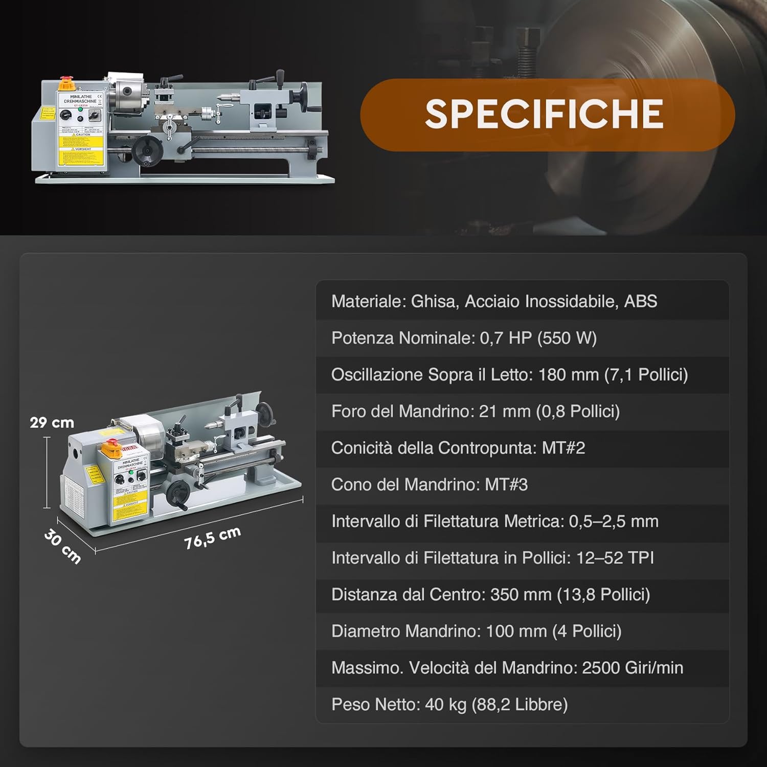
Figure 7: Dimensional diagram and key specifications of the lathe.
9. Warranty and Support
CREWORKS products are designed for durability and performance. For warranty information, technical support, or to order replacement parts, please contact CREWORKS customer service through their official website or the retailer where you purchased the product.
Please have your model number (MLMNX14DE) and purchase date available when contacting support.
Related documentsMLMNX14DE

Ask a question about this manual
Ask about setup, troubleshooting, compatibility, parts, safety, or missing instructions. Manuals+ will review the question and use this page’s manual context to help answer it.