1. Introduction
The Proster Smart Clamp Meter UA308E is a versatile auto-ranging digital clamp meter designed for precise electrical measurements. It features a 6000-count display, capable of measuring AC/DC voltage and current up to 800A, resistance, capacitance, frequency, and temperature. Key functions include diode test, continuity test, NCV (Non-Contact Voltage) detection, Live wire detection, data hold, flashlight, and auto power-off. The large HD color screen with an analog bar display ensures clear readability in various lighting conditions. It is powered by 3 AAA batteries and comes with essential accessories for comprehensive testing.
2. Safety Information
Please read and understand all safety warnings and operating instructions before using this instrument. Failure to follow these instructions may result in electric shock, fire, or serious injury.
- Always measure current through a single wire only. Attempting to measure multiple wires simultaneously will result in inaccurate readings (typically zero or incorrect values).
- Do not use the meter if it or the test leads appear damaged.
- Do not apply more than the rated voltage, as marked on the meter, between the terminals or between any terminal and earth ground.
- Exercise extreme caution when working with voltages above 60V DC or 30V AC RMS. Such voltages pose a shock hazard.
- Always disconnect power to the circuit and discharge all high-voltage capacitors before performing resistance, continuity, diode, or capacitance tests.
- Remove the test leads from the meter before opening the battery cover or case.
- Replace the batteries as soon as the low battery indicator appears to ensure accurate readings.
3. Package Contents
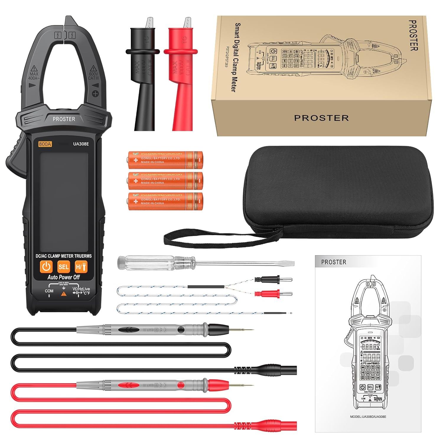
This image shows the Proster Smart Clamp Meter UA308E along with all its included accessories, such as test leads, thermocouple, batteries, fabric case, alligator clips, and a screwdriver, neatly laid out on a surface.
The package for your Proster Smart Clamp Meter UA308E should contain the following items:
- 1 x Proster Smart Clamp Meter (Model: UA308E)
- 1 x Type K Thermocouple
- 1 x Pair of Test Leads (Red and Black)
- 3 x 1.5V AAA Batteries
- 1 x User Manual
- 1 x Fabric Carrying Case
- 1 x Pair of Alligator Clips
- 1 x Screwdriver

A close-up view of the Proster Smart Clamp Meter UA308E, showcasing its main body, the clamp jaw, and the input jacks for test leads. The image also includes the test leads, batteries, and a carrying case.
4. Product Features
- Smart Mode & Multifunction: Automatically recognizes AC/DC voltage, DC/AC current, resistance, and continuity. Capable of measuring AC/DC voltage, DC/AC current, resistance, continuity, capacitance, diode, NCV, Live wire, and temperature.
- Advanced Design: Includes data hold function, built-in flashlight for low-light conditions, and automatic power-off to conserve battery life.
- Large HD Color Screen: Features a clear, high-definition color display with an analog bar graph, providing easy readability even in challenging environments.
- Wide Current Measurement Range: Measures DC/AC current up to 800A, suitable for a broad range of applications.
- True RMS: Provides accurate readings for non-sinusoidal waveforms.
- Compact and Portable: Designed to be lightweight with a 26mm clamp opening, making it easy to handle and transport with the included fabric case.

This image highlights the various functions of the Proster Clamp Meter, including HD backlight, AC/DC voltage, AC/DC current, Hertz, Buzzer, Resistance, Diode, Capacitance, Flashlight, Temperature, NCV induction, and Zero Fire Wire (Live test).

A detailed view of the Proster Clamp Meter's large HD color screen, showing the digital readings and the analog bar display, which provides a quick visual representation of the measured value.
5. Specifications
| Parameter | Specification |
|---|---|
| Maximum Display | 6000 Counts |
| DC Voltage (DCV) | 600mV/6V/60V/600V ± (0.5%+3) |
| AC Voltage (ACV) | 6V/60V/600V ± (0.8%+5) |
| DC Current (DCA) | 60A/800A ± (3.0%+10) |
| AC Current (ACA) | 60A/800A ± (3.0%+10) |
| Resistance | 600Ω/6kΩ/60kΩ/600kΩ/6MΩ/60MΩ ± (1.2%+2) |
| Capacitance | 6nF/60nF/600nF/6uF/60uF/600uF/6mF/60mF ± (3.0%+5) |
| Frequency | 10Hz/100Hz/1kHz/10kHz/100kHz/1MHz/10MHz ± (0.5%+2) |
| Temperature | -20°C to 1000°C (-4°F to 1832°F) ± (2.5%+5) |
| Clamp Opening | 26 mm |
| Diode Test | Yes |
| Continuity Test | Less than 50Ω ± 10Ω |
| Low Battery Indicator | Yes (approx. < 2.4V) |
| Data Hold | Yes |
| NCV (Non-Contact Voltage) | Yes |
| Auto Power Off | Approx. 15 minutes |
| True RMS | Yes |
| Clamp Light | Yes |
| Backlit Screen | Yes |
| Input Impedance | 10 MΩ |
| Sampling Rate | 3 times/second |
| AC Frequency Response | Voltage 40 – 1 kHz |
| Operating Method | Auto or Manual Ranging |
| Color | Orange and Black |
| Dimensions (L x W x H) | 18.4 x 6.6 x 3.48 cm |
| Weight | 22 Grams |
| Power Source | 3 x 1.5V AAA Batteries |
| Maximum Operating Voltage | 600 Volts |
6. Setup
6.1. Battery Installation
- Ensure the meter is turned off.
- Locate the battery compartment cover on the back of the meter.
- Use the included screwdriver to loosen the screw securing the battery cover.
- Remove the cover.
- Insert three 1.5V AAA batteries, observing the correct polarity (+ and -) as indicated inside the compartment.
- Replace the battery cover and tighten the screw.
6.2. Connecting Test Leads
For voltage, resistance, capacitance, diode, and continuity measurements:
- Insert the red test lead into the "VΩHzLive" input jack.
- Insert the black test lead into the "COM" input jack.
For temperature measurements, connect the Type K thermocouple to the appropriate input jacks as indicated on the meter.
7. Operating Instructions
7.1. Power On/Off
Press the power button to turn the meter on. The meter will enter Smart Mode by default. To turn off, press and hold the power button, or the meter will automatically power off after approximately 15 minutes of inactivity.
7.2. Measurement Functions
The UA308E features an intelligent auto-ranging mode that automatically identifies the measurement type. You can also manually select functions using the "SEL" button.
7.2.1. AC/DC Current Measurement (Clamp)

This image demonstrates the Proster Clamp Meter's ability to measure 800A AC/DC current by clamping around a single conductor. The built-in flashlight is also shown illuminating the measurement area.
- Turn the rotary switch to the current measurement range (e.g., 800A).
- Open the clamp jaw by pressing the trigger.
- Place the clamp around a single conductor (wire) through which the current is flowing. Ensure the jaw is completely closed.
- Read the current value on the display.
- Important: Only clamp around a single conductor. Clamping around multiple conductors (e.g., a power cord with live and neutral wires) will result in a zero or inaccurate reading.
7.2.2. AC/DC Voltage Measurement

Two Proster Clamp Meters are shown, one performing a DC voltage measurement on a battery using test leads, and the other performing an AC voltage measurement on a wall outlet, also using test leads.
- Connect the test leads as described in Section 6.2.
- Turn the rotary switch to the voltage measurement range (V~ for AC, V- for DC, or use Smart Mode).
- Connect the test leads in parallel to the circuit or component you wish to measure.
- Read the voltage value on the display.
7.2.3. Resistance, Diode, Continuity, Capacitance Measurement
- Connect the test leads as described in Section 6.2.
- Turn the rotary switch to the appropriate function (e.g., Ω for resistance, diode symbol for diode, buzzer symbol for continuity, F for capacitance, or use Smart Mode).
- Ensure the circuit or component is de-energized before connecting the test leads.
- Connect the test leads across the component to be measured.
- Read the value on the display. For continuity, a beep indicates a continuous circuit.
7.2.4. NCV (Non-Contact Voltage) Test
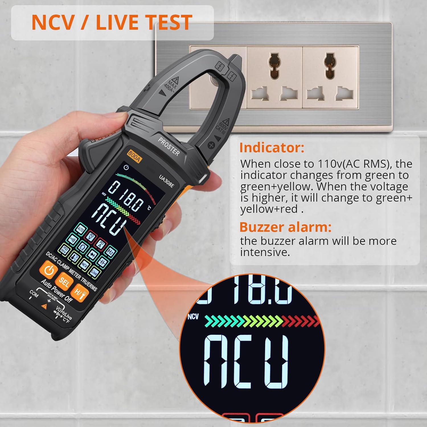
The Proster Clamp Meter is shown performing an NCV (Non-Contact Voltage) test near a wall outlet. The display indicates NCV detection, and the indicator lights change color (green, yellow, red) and the buzzer alarm intensifies as the voltage source is approached.
- Turn the rotary switch to the NCV function.
- Move the top part of the clamp meter close to the conductor or outlet you want to test for AC voltage.
- The meter will indicate the presence of AC voltage through visual (LEDs changing color from green to green+yellow to green+yellow+red) and audible (buzzer alarm) signals. The intensity of the alarm increases with stronger voltage.
7.2.5. Temperature Measurement

A Proster Clamp Meter is shown with its Type K thermocouple inserted into a liquid reservoir, demonstrating its temperature measurement capability. The display shows the temperature reading in both Fahrenheit and Celsius.
- Connect the Type K thermocouple to the designated input jacks on the meter.
- Turn the rotary switch to the temperature function (°C/°F).
- Place the tip of the thermocouple on or in the object whose temperature you wish to measure.
- Read the temperature value on the display.
7.3. Data Hold Function
Press the "H/T" button to hold the current reading on the display. Press it again to release the hold and resume live measurements.
7.4. Flashlight
Press the flashlight button (usually integrated with the power button or a dedicated button) to turn the built-in flashlight on or off, assisting in low-light work areas.
8. Maintenance
8.1. Cleaning
- Wipe the meter's case with a damp cloth and mild detergent. Do not use abrasives or solvents.
- Keep the input terminals and clamp jaw clean and free of dust or debris.
8.2. Battery Replacement
When the low battery indicator appears on the display, replace the batteries immediately to ensure accurate measurements and proper operation. Refer to Section 6.1 for battery installation instructions.
8.3. Storage
If the meter is not used for an extended period, remove the batteries to prevent leakage and damage. Store the meter in its fabric carrying case in a cool, dry place, away from direct sunlight and extreme temperatures.
9. Troubleshooting
| Problem | Possible Cause | Solution |
|---|---|---|
| Meter does not power on. | Dead or incorrectly installed batteries. | Check battery polarity or replace with new AAA batteries. |
| Inaccurate current reading (e.g., zero or very low). | Clamping around multiple conductors (e.g., a power cord). | Ensure the clamp is around a single live conductor only. |
| "OL" (Overload) displayed. | Measured value exceeds the selected range. | Switch to a higher range if available, or ensure the measurement is within the meter's capabilities. |
| No continuity beep. | Open circuit or high resistance. | Check the circuit for breaks or high resistance points. Ensure test leads are properly connected. |
| NCV not detecting voltage. | Voltage too low or meter not close enough to the source. | Ensure the meter's NCV sensor is very close to the live conductor. Test with a known live source. |
10. Warranty and Support
Proster products are designed and manufactured to the highest quality standards. For information regarding warranty coverage, technical support, or service, please refer to the warranty card included with your product or visit the official Proster website. Keep your purchase receipt as proof of purchase for warranty claims.
For further assistance, you may contact Proster customer support through their official channels. Details can typically be found on the product packaging or the manufacturer's website.
Note: The user manual included in the package may contain specific warranty details for your region.


