
NJTY S471
NJTY S471 Analog Multimeter User Manual
Model: S471
Introduction
The NJTY S471 Analog Multimeter is a versatile and reliable instrument designed for precise electrical measurements. It features a classic analog needle display, providing immediate visual feedback for fluctuating signals, which is particularly useful for trend analysis. This manual provides comprehensive instructions for the safe and effective operation, maintenance, and troubleshooting of your S471 multimeter.

Figure 1: NJTY S471 Analog Multimeter with included test leads and user manual.
Safety Information
Always adhere to the following safety precautions to prevent personal injury or damage to the multimeter:
- Do not exceed the maximum input values for any range.
- Ensure the correct function and range are selected before making measurements.
- Inspect test leads for damage before each use. Replace if insulation is compromised.
- Do not use the multimeter if it appears damaged or is not operating correctly.
- Exercise extreme caution when working with live circuits. High voltages can be lethal.
- Keep hands and fingers behind the probe barriers during measurements.
- Replace batteries and fuses only with the specified type and rating.
- Avoid using the multimeter in wet environments or during electrical storms.
Product Overview
The S471 Analog Multimeter features a clear, easy-to-read dial and intuitive controls for various measurement functions.

Figure 2: Key components and controls of the S471 Analog Multimeter.
Components and Controls:
- Dial: Displays measurement readings.
- Mechanical Zero Adjuster: Used to set the needle to zero before resistance measurements.
- Transistor hFE Measurement Socket: For testing transistor gain.
- Gear Knob (20 gears): Selects the measurement function and range.
- DC current "DCmA/0.5V" Jack: Input for DC current measurements.
- Voltage Resistance "V/Ω/BATT" Jack: Input for voltage, resistance, and battery measurements.
- Common Terminal "COM" Jack: Common (negative) input for all measurements.
- 0Ω Adjust Knob: Used to zero the meter for resistance measurements.
- Spare Fuse (Φ5x20 0.5A inside the box): Extra fuse for replacement.
- Working fuse (Φ5x20 0.5A inside the box): Active fuse for protection.
- 2*1.5V AAA battery Slot: Battery compartment.
- Spare Fuse (Φ5x20 0.5A inside the box): Additional spare fuse.

Figure 3: Detailed view of the analog dial for precise readings.
Setup
Battery Installation:
The S471 Multimeter requires two 1.5V AAA batteries for operation. These are typically included.
- Locate the battery compartment on the back of the multimeter.
- Open the battery cover.
- Insert two 1.5V AAA batteries, ensuring correct polarity (+ and -).
- Close the battery cover securely.
Connecting Test Leads:
Connect the red and black test leads to the appropriate jacks on the multimeter:
- Insert the black test lead into the "COM" (Common) jack.
- Insert the red test lead into the "V/Ω/BATT" jack for voltage, resistance, or battery measurements.
- For DC current measurements, insert the red test lead into the "DCmA/0.5V" jack.
Operating Instructions
Before each measurement, ensure the meter's needle is at the zero mark. Use the Mechanical Zero Adjuster if necessary. For resistance measurements, also use the 0Ω Adjust Knob to zero the meter after selecting the resistance range and shorting the test leads.
1. DC/AC Voltage Measurement:
- Set the Gear Knob to the desired DCV or ACV range (e.g., 10V, 50V, 250V, 1000V).
- Connect the red test lead to the "V/Ω/BATT" jack and the black test lead to the "COM" jack.
- Connect the test probes in parallel across the circuit or component to be measured.
- Read the voltage value from the corresponding scale on the dial.
Figure 4: Example of AC/DC Voltage measurement.
2. DC Current Measurement:
- Set the Gear Knob to the desired DCmA range (e.g., 2.5mA, 25mA, 500mA).
- Connect the red test lead to the "DCmA/0.5V" jack and the black test lead to the "COM" jack.
- Connect the test probes in series with the circuit where current is to be measured.
- Read the current value from the corresponding scale on the dial.
3. Resistance Measurement:
- Set the Gear Knob to the desired Ω (Ohms) range (e.g., x1, x10, x100, x1K, x10K).
- Connect the red test lead to the "V/Ω/BATT" jack and the black test lead to the "COM" jack.
- Short the test probes together and use the 0Ω Adjust Knob to set the needle to zero on the resistance scale.
- Connect the test probes across the component to be measured (ensure power is off for circuit components).
- Read the resistance value from the Ω scale and multiply by the selected range multiplier.

Figure 5: Example of Resistance measurement.
4. Continuity Test:
- Set the Gear Knob to the "Continuity" (speaker icon) range.
- Connect the red test lead to the "V/Ω/BATT" jack and the black test lead to the "COM" jack.
- Touch the test probes to the two points you want to check for continuity.
- An audible beep indicates continuity (low resistance).
Figure 6: Performing a continuity test.
5. Transistor hFE Gain Measurement:
- Set the Gear Knob to the "hFE" range.
- Identify the type of transistor (NPN or PNP) and its emitter (E), base (B), and collector (C) leads.
- Insert the transistor leads into the corresponding holes in the hFE Measurement Socket.
- Read the hFE value from the hFE scale on the dial.

Figure 7: Measuring transistor hFE gain.
6. Battery/Load Test:
- Set the Gear Knob to the "BATT" range (e.g., 1.5V, 9V).
- Connect the red test lead to the "V/Ω/BATT" jack and the black test lead to the "COM" jack.
- Connect the test probes across the battery terminals, observing polarity.
- Read the battery condition from the "BATT" scale (GOOD, WEAK, BAD).
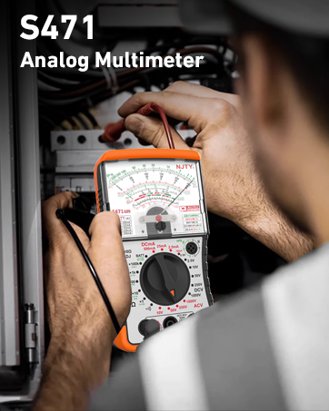
Figure 8: Testing battery condition.
7. dB Level Measurement:
- Set the Gear Knob to an ACV range (e.g., 10V ACV).
- Connect the red test lead to the "V/Ω/BATT" jack and the black test lead to the "COM" jack.
- Connect the test probes across the audio signal source.
- Read the dB level from the "dB" scale on the dial. Note that this measurement is relative to a reference level (typically 0dB = 1mW into 600Ω).
Maintenance
Cleaning:
Wipe the multimeter casing with a damp cloth and mild detergent. Do not use abrasives or solvents. Ensure the device is dry before storage or use.
Battery Replacement:
When the battery indicator shows low power or the meter does not function correctly, replace the batteries as described in the "Setup" section.
Fuse Replacement:
The S471 Multimeter is equipped with internal fuses for protection. If the meter stops functioning on a specific current or voltage range, a fuse may have blown. The device includes two spare fuses.
- Ensure the multimeter is disconnected from all circuits and turned off.
- Open the back casing of the multimeter (refer to the product overview diagram for fuse locations).
- Carefully remove the blown fuse.
- Replace it with a new fuse of the same type and rating (Φ5x20 0.5A).
- Securely close the back casing.

Figure 9: Location of the internal fuse for replacement.
Troubleshooting
| Problem | Possible Cause | Solution |
|---|---|---|
| Meter does not power on. | Dead or incorrectly installed batteries. | Check battery polarity and replace batteries. |
| No reading or incorrect reading. | Incorrect function/range selected; test leads not properly connected; blown fuse (for current/voltage ranges). | Verify function/range; ensure leads are fully inserted; check and replace fuses if necessary. |
| Needle does not zero for resistance. | 0Ω Adjust Knob not properly used; low battery. | Short leads and adjust 0Ω knob; replace batteries. |
| No continuity beep. | Open circuit; low battery. | Ensure circuit is closed; replace batteries. |
Specifications
- Model Number: S471
- Brand: NJTY
- Power Source: Battery Powered (2 x 1.5V AAA, included)
- Color: Yellow+Black
- Package Dimensions: 7.44 x 5.63 x 2.52 inches
- Item Weight: 14.07 ounces
- Upper Temperature Rating: 85 Degrees Celsius
- Measurement Functions: DC/AC Voltage, DC Current, Resistance, Transistor hFE, Capacitor, Battery Condition, Load Voltage/Current, dB Audio Levels, Continuity.
- Fuses: Φ5x20 0.5A (working fuse + 2 spare fuses)
What's in the Box
- 1 x NJTY S471 Pointer Multimeter
- 1 x Pair of Test Leads
- 1 x User Manual
- 2 x Spare Fuses (Φ5x20 0.5A)
- 2 x 1.5V AAA Batteries

Figure 10: Packaging and included items.
Warranty and Support
For warranty information and technical support, please refer to the contact details provided on the product packaging or visit the official NJTY website. Keep your purchase receipt for warranty claims.
Manufacturer: NJTY
Date First Available: December 18, 2024
Related documentsS471


Ask a question about this manual
Ask about setup, troubleshooting, compatibility, parts, safety, or missing instructions. Manuals+ will review the question and use this page’s manual context to help answer it.