Introduction
This manual provides essential information for the proper installation, operation, and maintenance of your CUIPPWRJ F722 BLS 60A V2 Stack. This integrated flight controller and electronic speed controller (ESC) unit is designed for racing drones, featuring an STM32F722 MCU, ICM42688-P gyroscope, and 16MB black box data storage. Please read this manual thoroughly before use to ensure optimal performance and safety.
Safety Information
Always observe the following safety precautions:
- Ensure all connections are correct before applying power. Incorrect wiring can cause damage to the unit and other components.
- Avoid short circuits. Handle the unit with care to prevent damage to sensitive electronic components.
- Do not operate the unit in wet conditions or expose it to extreme temperatures.
- Always disconnect the battery before performing any maintenance or modifications.
- This product is intended for experienced users in the hobby of remote-controlled drones. Improper use can lead to serious injury or property damage.
Package Contents
Verify that all items are present in your package:
- 1 x Flight Controller
- 1 x ESC (Electronic Speed Controller)
- 1 x Capacitor
- 1 x Air Unit Adapter
- 1 x Flight Controller Adapter
- 1 x Power Cable
- 4 x Screws (M3*30)
- 4 x Screws (M3*25)
- 8 x Nuts
- 8 x Grommets
- 2 x Cables
- 1 x Camera connection cable
Specifications
Flight Controller
- MCU: STM32F722
- IMU: ICM42688-P (SPI)
- Black Box: 16M onboard
- USB Connector: Type-C
- OSD: BetaFlight OSD with AT7456E chip
- BEC: 5V@3A, 9V@2.5A dual BEC
- Air Unit Connection: Direct connection to Air Unit
- Size: 36.85x36.85mm, hole 30.5x30.5mm
- Weight: 8.1g
Electronic Speed Controller (ESC)
- Input Voltage: 3-6S LiPo
- Continuous Current: 60A
- Burst Current: 65A (5 seconds)
- Support Protocol: Dshot 150/300/600
- Size: 42x45.7mm, hole 30.5x30.5mm
- Weight: 14.9g
General Product Information
- Package Dimensions: 1.18 x 0.79 x 0.39 inches
- Item Weight: 14.1 ounces
- Item Model Number: CUIPPWRJ123
- Manufacturer: CUIPPWRJ
Setup and Installation
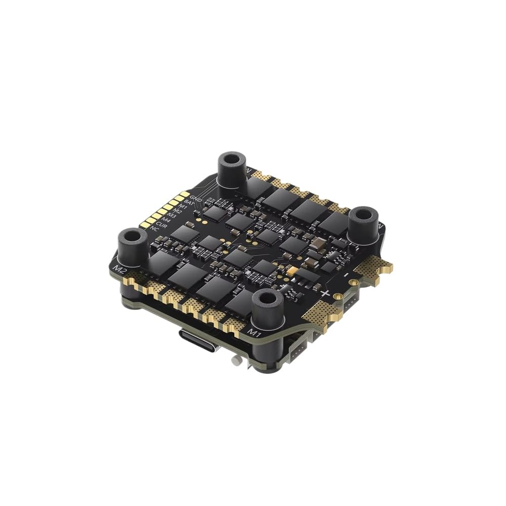
Figure 1: The CUIPPWRJ F722 BLS 60A V2 Stack, an integrated flight controller and ESC unit.
1. Physical Installation
Mount the F722 BLS 60A V2 Stack onto your drone frame using the provided screws, nuts, and grommets. Ensure the orientation is correct according to your flight controller software's settings. The stack is designed with 30.5x30.5mm mounting holes.

Figure 2: Side view of the F722 BLS 60A V2 Stack, illustrating its compact, two-board design for mounting.

Figure 3: Angled view of the assembled stack, showing the flight controller and ESC layers.
2. Wiring Connections
Connect the motors to the ESC pads (M1-M4). Connect the main battery lead to the designated BAT+ and BAT- pads on the ESC. Utilize the provided cables and adapters for connecting your camera, video transmitter (VTX), receiver (RX), and Air Unit to the flight controller. Refer to the pinout diagrams for precise connections.

Figure 4: Top view of the Flight Controller, detailing connection points for various drone components.

Figure 5: Bottom view of the ESC, showing motor and battery connection pads.
3. Software Configuration (BetaFlight)
Connect the flight controller to your computer using a Type-C USB cable. Open the BetaFlight Configurator software. Ensure the correct firmware target for the F722 MCU is selected. Configure your receiver, motors, OSD, and other settings as required for your drone build. The ESC supports Dshot 150/300/600 protocols.
Operating Instructions
1. Initial Power-Up and Arming
After completing all physical and software configurations, connect the drone battery. The flight controller will initialize. Ensure your radio transmitter is powered on and linked. Arm the drone only in a safe environment, away from people and obstacles.
2. Flight Data Recording (Black Box)
The integrated 16MB black box automatically records flight data. This data can be downloaded via BetaFlight Configurator for post-flight analysis, helping to diagnose performance issues or optimize tuning parameters. Connect the flight controller to your computer and navigate to the Blackbox tab in BetaFlight to access the logs.
Maintenance
- Regular Inspection: Periodically check all solder joints and connections for signs of wear, corrosion, or damage.
- Cleaning: Gently clean the boards with a soft brush or compressed air to remove dust and debris. Avoid using liquids.
- Firmware Updates: Keep your flight controller and ESC firmware updated to the latest stable versions. Refer to the BetaFlight and BLHeli_S/BLHeli_32 documentation for update procedures.
- Storage: Store the unit in a dry, cool environment when not in use.
Troubleshooting
- No Power: Check battery connection, polarity, and ensure no short circuits are present. Verify the main power cable is securely connected to the ESC.
- Motors Not Spinning:
- Ensure motors are correctly wired to the ESC.
- Verify ESC calibration and protocol settings in BetaFlight.
- Check motor direction and assignment in BetaFlight.
- No USB Connection: Try a different USB cable or port. Ensure BetaFlight Configurator is up-to-date. Install necessary drivers (e.g., STM32 Virtual COM Port Driver).
- Unstable Flight: Review black box logs for insights into flight controller performance. Check for vibrations, correct PID tuning, and proper propeller balance.
- OSD Issues: Verify OSD settings in BetaFlight. Ensure the AT7456E chip is recognized.
For further assistance, consult online forums, community resources, or the manufacturer's support channels.
Warranty and Support
For warranty information and technical support, please contact CUIPPWRJ customer service through their official website or the retailer where the product was purchased. Keep your proof of purchase for warranty claims.