1. Introduction
This manual provides detailed instructions for the safe and efficient operation of your KOMSHINE QX55-P PON Active OTDR and FX39 Core Alignment Fiber Optical Fusion Splicer. It also covers the included Optic Power Meter (KPM-35) and Optical Light Source (KLS-35). Please read this manual thoroughly before using the equipment to ensure proper functionality and to prevent damage or injury.
2. Safety Information
Always observe the following safety precautions when operating the KOMSHINE equipment:
- Laser Radiation: Never look directly into the optical output ports. Invisible laser radiation may be present and can cause severe eye damage. Use appropriate laser safety eyewear.
- Electrical Safety: Ensure the equipment is powered by the correct voltage and frequency. Do not operate with damaged power cords or in wet conditions.
- Sharp Objects: Fiber optic cleavers and stripped fibers have extremely sharp edges. Handle with care to avoid cuts. Dispose of fiber scraps properly in a designated container.
- Battery Safety: Use only approved batteries and chargers. Do not expose batteries to high temperatures or attempt to disassemble them.
- Ventilation: Ensure adequate ventilation around the fusion splicer during operation, especially during heating cycles.
3. Package Contents
Verify that all items listed below are included in your package:
- KOMSHINE QX55-P PON Active OTDR
- KOMSHINE FX39 Core Alignment Fiber Optical Fusion Splicer
- KOMSHINE KPM-35 Optic Power Meter
- KOMSHINE KLS-35 Optical Light Source
- Fiber Cleaver (FC-30)
- Fiber Strippers
- Alcohol Bottle and Wipes
- Power Adapters and Cords
- Carrying Case
- User Manuals and Calibration Certificates
- Other accessories as pictured

Figure 3.1: Complete KOMSHINE fiber optic tool kit, including the QX55-P OTDR, FX39 Fusion Splicer, power meter, light source, and various accessories.

Figure 3.2: The FX39 Fusion Splicer and its associated tools neatly organized within its protective green carrying case.

Figure 3.3: A visual representation of the standard package contents for the QX55-P OTDR, detailing each component from the carrying case to documentation.
4. Product Overview
4.1 KOMSHINE QX55-P PON Active OTDR
The QX55-P is a versatile Optical Time Domain Reflectometer designed for fiber optic network testing. It features 1310/1550/1625nm wavelengths with dynamic ranges of 32/30/28dB, respectively. It includes built-in Optical Power Meter (OPM), Visual Fault Locator (VFL) with 5-8km range, RJ45 function, and FIP modules. Key features include a 1m event dead zone, Link Map, and Pass/Fail judgment functions for efficient fault detection and analysis.

Figure 4.1: The KOMSHINE QX55-P OTDR, showcasing its user interface and robust design.

Figure 4.2: The multi-function display of the QX55-P OTDR, illustrating its various testing capabilities.

Figure 4.3: The QX55-P OTDR's Link Map function provides a graphical overview of fiber events, while the Splitter Test feature supports up to 1:32 splitters.
4.2 KOMSHINE FX39 Core Alignment Fiber Optical Fusion Splicer
The FX39 is a high-performance fusion splicer featuring six-motor core alignment for precise fiber splicing. It offers fast splicing in 6 seconds and rapid heating in 16 seconds. The device is equipped with a 4.3-inch LCD color display and a 7800mAh battery, providing approximately 400 cycles of splicing and heating on a single charge. It is designed for multi-FTTH projects and offers an average splice loss of 0.01dB.

Figure 4.4: The FX39 Fusion Splicer, emphasizing its speed and efficiency in fiber splicing and heating.
4.3 KOMSHINE KPM-35 Optic Power Meter & KLS-35 Optical Light Source
The KPM-35 is an optical power meter with a measurement range of -70 to +10dBm and supports 7 wavelengths (850/980/1300/1310/1490/1550/1625nm). The KLS-35 is a single-mode optical light source with 1310/1550nm wavelengths. These devices are essential for verifying optical power levels and signal integrity in fiber networks.
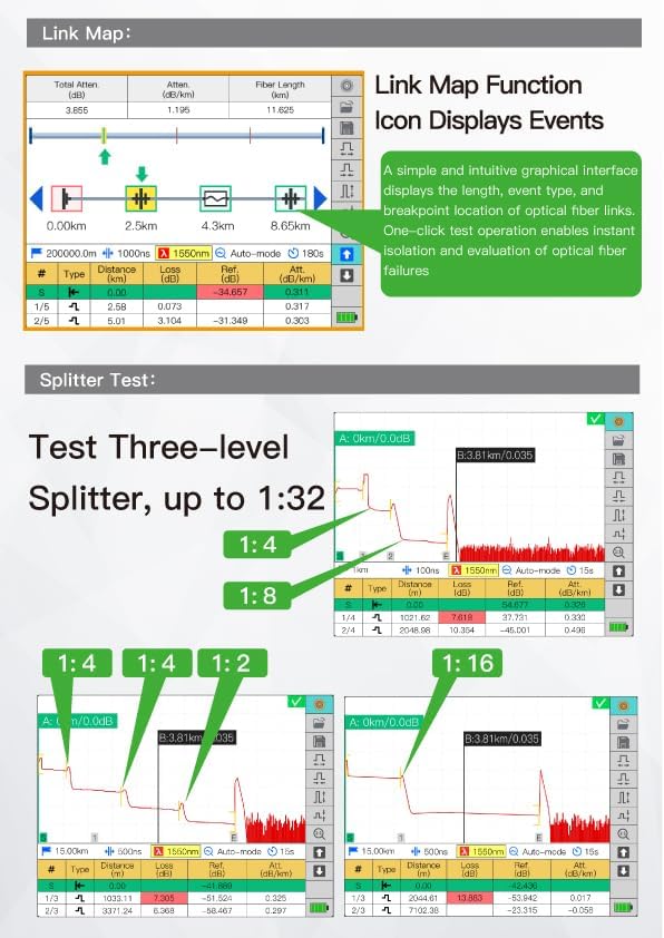
Figure 4.5: The KPM-35 Optical Power Meter and KLS-35 Optical Light Source, used for accurate fiber optic measurements.
5. Setup
5.1 Initial Setup and Charging
- Unpack: Carefully remove all components from the carrying case.
- Battery Installation: For the FX39 Splicer and QX55-P OTDR, ensure the battery is securely installed.
- Charging: Connect the appropriate power adapter to the device and a power outlet. Charge the batteries fully before first use. The FX39 battery (7800mAh) typically charges in approximately 3.5 hours.
- Power On: Press and hold the power button on each device to turn it on.
5.2 Preparing the Work Area
Set up the FX39 Fusion Splicer on a stable, clean surface. The carrying case for the FX39 can be converted into a working table for field operations.
6. Operating Instructions
6.1 QX55-P OTDR Operation
The QX55-P OTDR allows for precise measurement of fiber optic links. Follow these steps for a typical test:
- Connect Fiber: Connect the fiber under test to the OTDR's optical port. Ensure connectors are clean.
- Select OTDR Function: From the main menu, navigate to and select the OTDR testing function.
- Configure Settings: Adjust parameters such as wavelength (e.g., 1310nm, 1550nm, 1625nm), test range, pulse width, and test time (e.g., 15 seconds for average mode). The device supports automatic measurement mode.
- Start Test: Initiate the test. The OTDR will display the trace and an event table.
- Analyze Results: Review the trace for events like splices, connectors, and fiber breaks. The event table provides detailed information on distance, loss, and reflectance for each event. Utilize the Link Map function for a simplified graphical view and Pass/Fail judgment.
Video 6.1: This video demonstrates the operation of the KOMSHINE QX55 OTDR, including menu navigation, setting test parameters, connecting fiber, and interpreting the test results for a 140km fiber link. It shows how to view event tables and traces for different wavelengths.
6.2 FX39 Fusion Splicer Operation
The FX39 is designed for precise and reliable fiber fusion splicing. Follow these general steps:
- Fiber Preparation: Strip the fiber coating to the required length, clean the bare fiber with alcohol wipes, and cleave the fiber using the FC-30 cleaver to achieve a clean, perpendicular end-face.
- Place Fiber: Carefully place the prepared optical fibers into the splicing slots of the FX39. The splicer supports various fiber types including FTTH drop cable, bare fiber, 0.9mm fiber cable, and 3.0mm jump cable.
- Close Dust Cover: Close the dust cover. The splicer will automatically begin the alignment and splicing process.
- Splicing: The FX39 will perform core alignment and then arc fusion, typically completing in 6 seconds. The display will show the estimated splice loss.
- Heat Shrink: Move the heat shrink tube over the spliced joint and place it in the heating oven. The oven will heat the tube, protecting the splice, typically in 16 seconds.
- Cool Down: Remove the spliced fiber and allow it to cool down before handling.
Video 6.2: This video provides user guidance for the FX39 Six Motor Fusion Splicer, demonstrating the process of preparing fiber, placing it in the splicer, initiating the 6-second splicing, and performing the 16-second heat shrink process.
6.3 FC-30 Fiber Cleaver Operation
The FC-30 fiber cleaver is used to create a precise, flat, and perpendicular end-face on optical fibers, which is crucial for successful fusion splicing. It features a tungsten steel blade for durability and an auto-return mechanism for smooth cutting. The all-in-one fiber holder supports various fiber types.
- Prepare Fiber: Strip the fiber coating to the required length.
- Place Fiber: Open the cleaver's top clamp and place the bare fiber in the appropriate groove of the all-in-one fiber holder. Ensure the fiber is positioned correctly according to the measurement scale.
- Close Clamp: Close the top clamp to secure the fiber.
- Cleave: Push the cleaver blade mechanism across the fiber. The auto-return blade ensures a clean cut.
- Remove Fiber: Open the clamp and carefully remove the cleaved fiber.
Video 6.3: This video introduces the FC-30 fiber cleaver, demonstrating its features such as the tungsten steel blade, all-in-one fiber holder, auto-return blade, and ergonomic design for precise fiber preparation.
6.4 KPM-35 Power Meter & KLS-35 Light Source Operation
These devices are used together to measure optical loss in fiber optic cables.
- Connect KLS-35: Connect one end of a known good fiber patch cord to the KLS-35 Optical Light Source.
- Connect KPM-35: Connect the other end of the patch cord to the KPM-35 Optical Power Meter.
- Set Wavelength: Ensure both devices are set to the same operating wavelength (e.g., 1310nm or 1550nm).
- Reference Measurement: Take a reference power measurement with the patch cord directly connected. This establishes a baseline.
- Test Cable: Insert the fiber cable under test between the KLS-35 and KPM-35 (using additional patch cords if necessary).
- Measure Loss: Read the power level on the KPM-35. The difference between the reference power and the measured power is the optical loss of the cable under test.
7. Maintenance
Regular maintenance ensures the longevity and accuracy of your KOMSHINE equipment.
- Cleaning Optical Ports: Always keep optical connectors and ports clean. Use lint-free wipes and optical-grade alcohol. Contamination is a primary cause of measurement errors and poor splice quality.
- FX39 Electrode Cleaning/Replacement: Regularly inspect the splicer electrodes. Clean them as needed with a cotton swab and alcohol. Replace electrodes after approximately 5000 splices or if splice quality degrades significantly.
- Screen Cleaning: Clean the LCD screens with a soft, dry cloth. Avoid abrasive cleaners.
- Battery Care: Store batteries in a cool, dry place. If storing for extended periods, ensure they are partially charged (around 50%). Avoid fully discharging or overcharging.
- Calibration: Periodically calibrate the OTDR and power meter according to manufacturer recommendations or industry standards to maintain accuracy. The QX55-P and KPM-35 support self-calibration functions.
8. Troubleshooting
This section addresses common issues you might encounter.
- Poor Splice Loss (FX39):
- Ensure fiber end-faces are perfectly clean and cleaved.
- Check electrode condition; replace if worn or dirty.
- Verify fiber type settings match the actual fiber.
- Inaccurate OTDR Measurements (QX55-P):
- Clean OTDR optical port and launch fiber connectors.
- Verify correct wavelength and test range settings.
- Perform self-calibration if available.
- Device Not Powering On:
- Check battery charge level.
- Ensure battery is correctly installed.
- Verify power adapter connection if operating on AC power.
- VFL Not Working:
- Check if the VFL port is clean.
- Ensure VFL function is activated in the menu.
9. Specifications
| Component | Feature | Specification |
|---|---|---|
| QX55-P OTDR | Wavelengths | 1310/1550/1625nm |
| Dynamic Range | 32/30/28dB | |
| Event Dead Zone | 1m | |
| Built-in Functions | OPM, VFL (5-8km), RJ45, FIP | |
| Splitter Test | Up to 1:16/32 | |
| FX39 Fusion Splicer | Splicing Time | 6 seconds |
| Heating Time | 16 seconds | |
| Display | 4.3 inch LCD color display | |
| Battery Capacity | 7800mAh (400 cycles) | |
| Average Splice Loss | SM: 0.02dB / MM: 0.01dB / DS: 0.04dB / NZDS: 0.04dB / G.657: 0.02dB | |
| KPM-35 Power Meter | Measurement Range | -70 to +10dBm |
| Wavelengths | 850/980/1300/1310/1490/1550/1625nm | |
| Accuracy | High Precision 0.2dB | |
| KLS-35 Light Source | Wavelengths | 1310/1550nm |
| Typical Output Power | -5dB |
10. Warranty and Support
KOMSHINE products are manufactured to high-quality standards. For warranty information, technical support, or service inquiries, please refer to the warranty card included with your product or contact KOMSHINE customer service directly. Please have your product model and serial number available when contacting support.


