1. Introduction
This manual provides comprehensive instructions for the installation, configuration, and operation of the CUIPPWRJ GEP-F722-BT-HD V2 Flight Controller. Designed for DIY RC quadcopters and freestyle drones, this flight controller features an STM32F722RET6 MCU, 3-6S LiPo compatibility, and a Type-C USB connector. Please read this manual thoroughly before use to ensure proper functionality and safety.
2. Specifications
- MCU: STM32F722RET6
- IMU: 42688-P (SPI)
- Black Box: 512MB onboard SD card
- USB Connector: Type-C
- OSD: OSD with AT7456E chip
- BEC Output: 5V 3A / 12V 3A
- Filtering: Integrated filtering
- Firmware: GEPRCF722-BT-HD
- Size: 36x36mm, φ4mm hole becomes φ3mm after using grommets
- Input Voltage: LiPo 3-6S
- UARTs: 5
- Package Dimensions: 1.18 x 0.79 x 0.39 inches
- Item Weight: 14.1 ounces
3. Key Features
- Advanced STM32F722RET6 processor for superior performance.
- Wide input voltage compatibility (3-6S LiPo) for diverse drone setups.
- Integrated 5V 3A and 12V 3A BEC outputs for powering peripherals.
- Onboard 512MB black box for flight data logging.
- Type-C USB connector for convenient configuration.
- Built-in OSD with AT7456E chip for on-screen display.
- Compact 36x36mm size with φ4mm to φ3mm mounting holes.
4. Package Contents
The package includes:
- 1 x CUIPPWRJ GEP-F722-BT-HD V2 Flight Controller
5. Pinout Diagram and Connections
Refer to the diagram below for the pinout and connection points of the GEP-F722-BT-HD V2 Flight Controller. Proper connection is essential for safe and reliable operation.
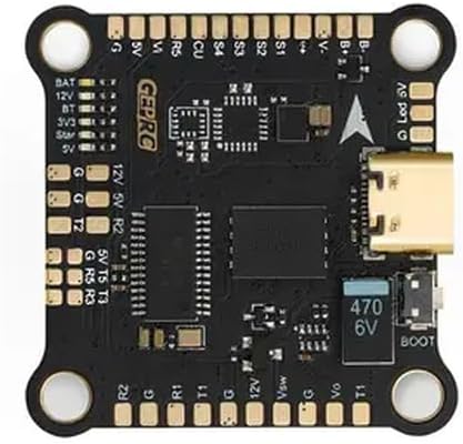
Image Description: A top-down view of the black GEP-F722-BT-HD V2 Flight Controller board. It features various solder pads and connectors around its perimeter. Key labels visible include BAT, 12V, 5V, 3V3, G (Ground), T (Transmit), R (Receive) for UARTs, S1-S4 for motor outputs, and a Type-C USB port on the right side. A "BOOT" button and a 470 6V capacitor are also visible near the USB port. The "GEPRC" logo is printed on the board.
5.1. Pin Descriptions
| Pin Label | Description |
|---|---|
| BAT | Battery Voltage Input (3-6S LiPo) |
| 12V | 12V BEC Output (3A max) |
| 5V | 5V BEC Output (3A max) |
| 3V3 | 3.3V Output |
| G | Ground |
| BT | Bluetooth (if applicable, check firmware) |
| S1-S4 | Motor Signal Outputs (PWM) |
| R1, T1 | UART1 Receive and Transmit |
| R2, T2 | UART2 Receive and Transmit |
| R3, T3 | UART3 Receive and Transmit |
| R5, T5 | UART5 Receive and Transmit |
| CU | Current Sensor Input |
| Vsw | Video Switch (if applicable) |
| Vo | Video Output |
| BOOT | Bootloader Button (for DFU mode) |
| Led V | LED Strip Voltage Output |
6. Setup and Configuration
6.1. Physical Installation
- Mount the flight controller onto your drone frame using the provided grommets to reduce vibrations. Ensure the arrow on the FC points towards the front of the drone.
- Connect motor ESC signal wires to the corresponding S1-S4 pads.
- Connect the battery power lead (VBAT) to the BAT and G pads.
- Connect your receiver (e.g., SBUS, CRSF, PPM) to an available UART (e.g., R2/T2).
- Connect your VTX (Video Transmitter) to a 5V or 12V output, Ground, and Video Out (Vo) pad.
- Connect your FPV camera to a 5V or 12V output, Ground, and Video In (Vsw or similar, depending on setup).
- Connect any other peripherals (GPS, LED strips) to appropriate UARTs or power outputs.
6.2. Firmware Flashing and Configuration
- Download and install the latest Betaflight Configurator software on your computer.
- Connect the flight controller to your computer using a Type-C USB cable.
- If the flight controller is not recognized, you may need to install DFU drivers. Press and hold the BOOT button while plugging in the USB cable to enter DFU mode.
- In Betaflight Configurator, select the correct firmware target (GEPRCF722-BT-HD) and flash the latest stable firmware.
- After flashing, connect to the flight controller and perform initial configuration:
- Calibrate the accelerometer.
- Configure UARTs for your receiver, VTX, GPS, etc.
- Set up motor protocols (e.g., DShot).
- Configure OSD elements.
- Perform a full backup of your configuration.
7. Operating Instructions
Once the flight controller is installed and configured, follow these steps for operation:
- Ensure all connections are secure and correct.
- Power on your radio transmitter.
- Connect the LiPo battery to your drone. The flight controller will power up.
- Verify that your FPV feed is clear and OSD information is displayed correctly.
- Arm the drone using your configured arming switch on the transmitter.
- Perform pre-flight checks, including motor direction and control surface response.
- Fly responsibly and within legal limits.
- After flight, disarm the drone and disconnect the LiPo battery.
8. Maintenance
- Regularly inspect solder joints for cracks or cold joints.
- Keep the flight controller clean and free from dust, dirt, and moisture.
- Avoid exposing the board to extreme temperatures or static discharge.
- Periodically check for and update to the latest stable firmware versions.
- Ensure all mounting screws are secure but not overtightened.
9. Troubleshooting
- No Power: Check battery connection, polarity, and ensure the battery is charged. Inspect for shorts.
- Not Connecting to Betaflight: Ensure correct drivers are installed. Try a different USB cable or port. Enter DFU mode by holding the BOOT button while plugging in.
- Motors Not Spinning: Verify ESC connections, motor protocol in Betaflight, and ensure the drone is armed. Check motor direction.
- No FPV Feed: Check camera and VTX connections, power to VTX/camera, and ensure correct video input/output settings in Betaflight OSD.
- Unstable Flight: Re-check mounting for vibrations, recalibrate accelerometer, verify PID settings, and ensure propellers are undamaged and balanced.
10. Warranty and Support
For warranty information and technical support, please refer to the manufacturer's official website or contact your retailer. Keep your proof of purchase for any warranty claims.


