1. Introduction
The Wanptek KPS6020D is a high-performance, adjustable, regulated switching DC power supply designed for precision applications. It offers accurate control over voltage and current, making it suitable for various uses including school lab experiments, cell phone repair, electronics production, and lab measurements. This manual provides detailed instructions for the safe and efficient operation of your KPS6020D power supply.
2. Product Overview
2.1 Front Panel Layout
The front panel of the KPS6020D features all necessary controls and indicators for operation.

Figure 2.1: Front Panel Introduction. This image shows the front panel of the power supply, highlighting the OCP status indicator, OCP switch, Output status display, Output switch, Encoder adjustment knob for voltage, Encoder adjustment knob for current, and the Power button.
- Power Button: Turns the unit on or off.
- OCP (Over Current Protection) Switch: Activates or deactivates the over current protection feature.
- OCP Status Indicator: LED light indicating OCP status.
- Digital Display: Shows real-time voltage (V) and current (A) output values.
- Output Switch: Controls the output power to the terminals.
- Output Status Display: LED light indicating output status (on/off).
- Encoder Adjustment Knobs (Voltage/Current): Used to precisely set the desired voltage and current limits. Pressing the knob allows selection of the digit to adjust, and turning it changes the value.
2.2 Rear Panel Connections
The rear panel provides the main power input and output terminals.

Figure 2.2: Rear Panel Connections. This image illustrates the output negative (-) and output positive (+) terminals, along with the AC power input and the fuse box location on the rear of the power supply.
- Output Positive (+): Red terminal for positive output connection.
- Output Negative (-): Black terminal for negative output connection.
- AC Power Input: Standard AC power cord connection.
- Fuse Box: Contains the replaceable fuse for circuit protection.
2.3 Dimensions
Understanding the physical dimensions of the unit is important for placement and integration into your workspace.

Figure 2.3: Product Dimensions. This image shows the power supply with its approximate dimensions: 200mm width, 105mm height, and 275mm depth. It also shows the included 120cm output cables.
3. Features
- High Precision: Offers precise voltage and current control with a resolution of 0.01V and 0.01A, ensuring accurate power delivery.
- Adjustable Voltage and Current: Allows fine-tuning of output voltage from 0 to 60V and output current from 0 to 20A, providing flexibility for different requirements.
- Dual Display: Features a clear digital display for both voltage and current readings, enabling easy monitoring and control.
- Switching Technology: Utilizes efficient switching technology to minimize power loss and heat generation.
- Overload Protection: Equipped with multiple protection mechanisms, including overvoltage, overcurrent, overload, over-temperature, and short-circuit protection, safeguarding your devices and the power supply itself.
- Smart Fan: Integrated smart fan for efficient cooling and low noise operation.
- Rugged and Durable Design: Built for longevity and reliable performance.
- Constant Voltage and Current Modes: Operates in both Constant Voltage (CV) and Constant Current (CC) modes.
- Compact and Lightweight: Small footprint suitable for benchtop use and rack installation.
4. Setup
- Unpacking: Carefully remove the power supply and all accessories from the packaging. Verify that all items listed in the "Package Contents" section are present.
- Placement: Place the power supply on a stable, level surface with adequate ventilation. Ensure there is sufficient space around the unit for airflow, especially around the fan vents.
- Power Connection: Connect the provided AC power cord to the AC power input on the rear panel of the power supply, then plug the other end into a suitable grounded AC outlet.
- Initial Check: Before connecting any load, turn on the power supply using the front panel power button. The display should illuminate, showing default voltage and current settings.
5. Operating Instructions
5.1 Adjusting Voltage and Current
The KPS6020D uses encoder adjustment knobs for precise setting of output parameters.

Figure 5.1: Encoder Knob Adjustment. This image demonstrates how to adjust the voltage and current settings. First, press the knob to select the digit to be adjusted. Second, turn the knob to change the value of the selected digit.
- Select Parameter: The top display shows voltage, and the bottom shows current. To adjust either, press the corresponding encoder knob (Voltage or Current).
- Select Digit: Each press of the knob will cycle through the digits of the displayed value, indicating which digit is currently active for adjustment.
- Adjust Value: Once a digit is selected, turn the knob clockwise to increase the value or counter-clockwise to decrease it.
- Confirm Setting: After setting the desired voltage and current, the values will be stored automatically.
5.2 Over Current Protection (OCP)
The OCP feature protects your load and the power supply from excessive current.

Figure 5.2: OCP Functionality. This image illustrates the OCP button and explains that when OCP is switched on, if the external load is short-circuited or the output current exceeds the limit, the power supply automatically switches off the output and issues an alarm.
- Activating OCP: Press the OCP switch on the front panel to enable this protection. The OCP status indicator will light up.
- OCP Trigger: If the external load is short-circuited or the output current exceeds the preset limit while OCP is active, the power supply will automatically cut off the output and emit an alarm.
- Resetting OCP: To clear an OCP event, resolve the issue with the load, then press the OCP switch again or cycle the power.
5.3 Output Switch
The output switch provides a convenient way to enable or disable power to your connected load without changing voltage/current settings.
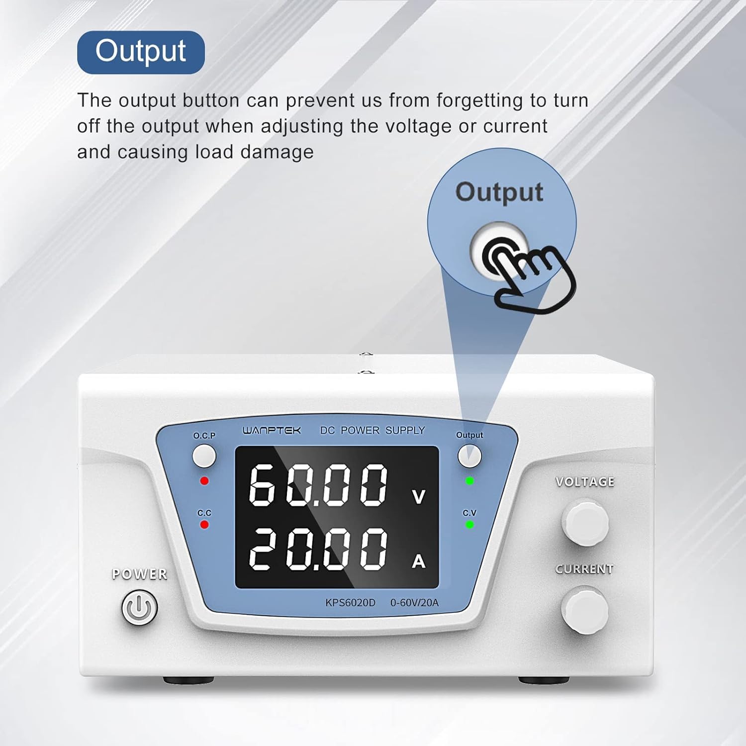
Figure 5.3: Output Button. This image highlights the Output button and explains its purpose: it prevents accidental load damage by allowing the user to turn off the output when adjusting voltage or current.
- Enabling Output: Press the Output switch to supply power to the output terminals. The Output status indicator (green LED) will light up.
- Disabling Output: Press the Output switch again to cut off power to the output terminals. This is useful when making adjustments or connecting/disconnecting loads to prevent accidental damage.
6. Maintenance
- Cleaning: Use a soft, dry cloth to clean the exterior of the power supply. Do not use abrasive cleaners or solvents.
- Ventilation: Ensure that the ventilation openings on the unit are not blocked. Periodically check for dust accumulation and gently clean with compressed air if necessary.
- Fuse Replacement: If the unit does not power on, check the fuse located in the fuse box on the rear panel. Replace it with a fuse of the same type and rating if blown. Always disconnect the power cord before replacing the fuse.
- Storage: When not in use for extended periods, store the power supply in a cool, dry place, away from direct sunlight and extreme temperatures.
7. Troubleshooting
| Problem | Possible Cause | Solution |
|---|---|---|
| Unit does not power on. | No AC power; Blown fuse; Power button not pressed. | Check AC power connection and outlet; Replace fuse (refer to Maintenance section); Ensure power button is fully pressed. |
| No output voltage/current. | Output switch off; OCP triggered; Incorrect settings. | Press the Output switch to enable output; Check OCP status and reset if triggered; Verify voltage and current settings are not set to zero. |
| Output voltage/current unstable. | Poor load connection; Overload condition; Internal fault. | Check and secure all output connections; Reduce load or increase current limit; If problem persists, contact support. |
| Unit overheats. | Blocked ventilation; Excessive load. | Ensure vents are clear and unit has adequate airflow; Reduce load to within specifications. |
8. Specifications
| Parameter | Value |
|---|---|
| Model | KPS6020D |
| Input Voltage | AC 220V (typical, check product label for exact range) |
| Output Voltage Range | 0 - 60V |
| Output Current Range | 0 - 20A |
| Output Power | 1200W |
| Voltage Resolution | 0.01V |
| Current Resolution | 0.01A |
| Display | Dual LED Digital Display |
| Protection Features | Overvoltage, Overcurrent, Overload, Over-temperature, Short-circuit |
| Cooling | Smart Fan |
| Product Dimensions (LxWxH) | Approx. 275 x 200 x 105 mm |
| Item Weight | 100 g |
| Country of Origin | China |
Note: Specifications are subject to change without prior notice. Please refer to the product label for the most accurate information.
9. Package Contents
Upon opening the package, ensure all the following items are included:
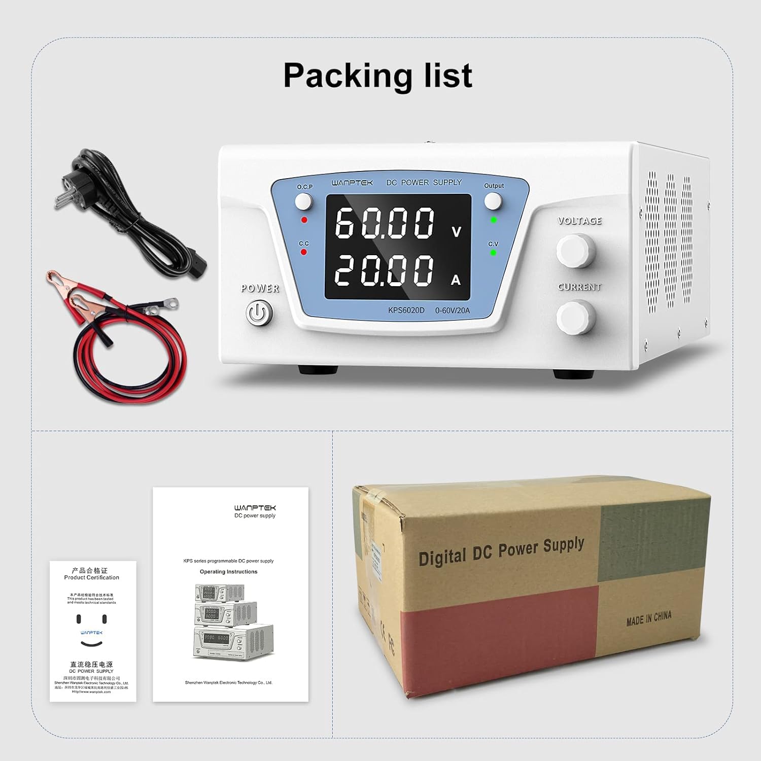
Figure 9.1: Packing List. This image displays the items typically included in the package: the Wanptek KPS6020D power supply unit, an AC power cord, output test leads (banana plug to alligator clip), and a user manual/product certification document.
- 1 x Wanptek KPS6020D 60V 20A Power Supply Unit
- 1 x AC Power Cord
- 1 x Output Test Leads (Banana Plug to Alligator Clip)
- 1 x User Manual / Product Certification Document
10. Safety Information
Please read and understand all safety warnings and operating instructions before using this power supply. Failure to do so may result in injury or damage to the unit or connected devices.
- Do not operate the unit in wet or damp conditions.
- Ensure proper grounding of the power supply.
- Do not open the casing of the power supply. There are no user-serviceable parts inside. Refer all servicing to qualified personnel.
- Avoid short-circuiting the output terminals, especially when the output is enabled.
- Always disconnect power before making or changing connections to the output terminals.
- Use the power supply within its specified voltage and current limits.
- Keep the unit away from flammable materials and explosive atmospheres.
11. Warranty and Support
Specific warranty terms and conditions for the IDUINO Wanptek KPS6020D power supply are not provided in this document. Please refer to the product packaging, purchase receipt, or contact your retailer or the manufacturer directly for warranty information and technical support.
For technical assistance or inquiries, please contact IDUINO customer support through their official channels.


