
Auxbeam AS-R40(WITHOUT APP)
Contents
Auxbeam AS-R40 Slim Switch Panel Instruction Manual
Model: AS-R40 (WITHOUT APP)
1. Introduction
This manual provides comprehensive instructions for the installation, operation, and maintenance of the Auxbeam 4 Gang Slim Switch Panel RGB AS-R40. This multifunction switch panel is designed for 12-24V vehicle applications, including trucks, off-road vehicles, cars, and marine vessels. It features RGB dimmable backlighting, multiple lighting modes (Toggle, Momentary, Pulsed), and a memory function for user convenience. The AS-R40 model does not support Bluetooth app control.

Image: Auxbeam AS-R40 Slim Switch Panel and its associated control box, showcasing the compact design and components.
2. Safety Information
Adherence to the following safety guidelines is crucial for safe operation and to prevent damage to the product or vehicle:
- Always disconnect the vehicle's battery before performing any electrical installation or maintenance.
- Ensure all wiring connections are secure and properly insulated to prevent short circuits.
- Do not exceed the maximum current rating of 60A or the maximum power rating (720W at 12V, 1400W at 24V) for the system.
- Install the control box in a location protected from direct water exposure, although it is designed to be waterproof.
- Verify the correct voltage (12-24V DC) of your vehicle's electrical system before connecting the switch panel.
- Use the provided resettable circuit breaker to protect against reverse polarity, overcurrent, overvoltage, and overheating.
- If you are unsure about any installation steps, consult a qualified automotive electrician.
3. Package Contents
The Auxbeam AS-R40 Slim Switch Panel package includes the following components:

Image: All components included in the Auxbeam AS-R40 package, neatly arranged for identification.
- AS-R40 Switch Panel
- Circuit Control Box
- Circuit Breaker
- 60 pcs Labels (Decals)
- Mounting Brackets
- Instruction Manual
- 10ft Wire Harness
- Power Harness, Fuse Wire & Adapter, Installation Kit
- Waterproof Cover
- Packing Box
- Double-sided Tape
- Screwdriver
- Screws
4. Product Features
The Auxbeam AS-R40 Slim Switch Panel is equipped with several features designed for enhanced control and user experience:
- Auto-Dimming RGB Backlight: The switch panel features customizable RGB backlight colors that automatically adjust brightness based on ambient light conditions, reducing eye strain.
- Three Lighting Modes:
- TOGGLE: Device remains continuously on.
- MOMENTARY: Device activates only while the button is pressed and held.
- PULSED: Device operates in a strobe or flashing mode.
- Backlight OFF Function: The backlight can be quickly deactivated with a single press of the "MODE" button.
- Memory Function: The "ON/OFF" button retains the last light settings, automatically restoring them when the panel is reactivated.
- Security Configuration: The control box incorporates built-in solid-state relays and includes a high-quality resettable circuit breaker for protection against reverse polarity, overcurrent, overvoltage, and overheating. A silicone protective cover is included for water resistance.
- Wide Application: Compatible with 12-24V vehicles, including trucks, boats, cars, buses, off-road vehicles, powersports, marine, ATVs, UTVs, SUVs, side-by-sides, and heavy-duty machinery.

Image: Illustration of the auto-dimming function, showing the switch panel's backlight adjusting to bright and dim surroundings.

Image: Visual representation of the three distinct lighting modes: Toggle for constant light, Momentary for temporary activation, and Pulsed for strobe effects.

Image: Diagram illustrating the advantages of built-in solid-state relays over traditional external relays, emphasizing the IP65 waterproof rating of the control box.
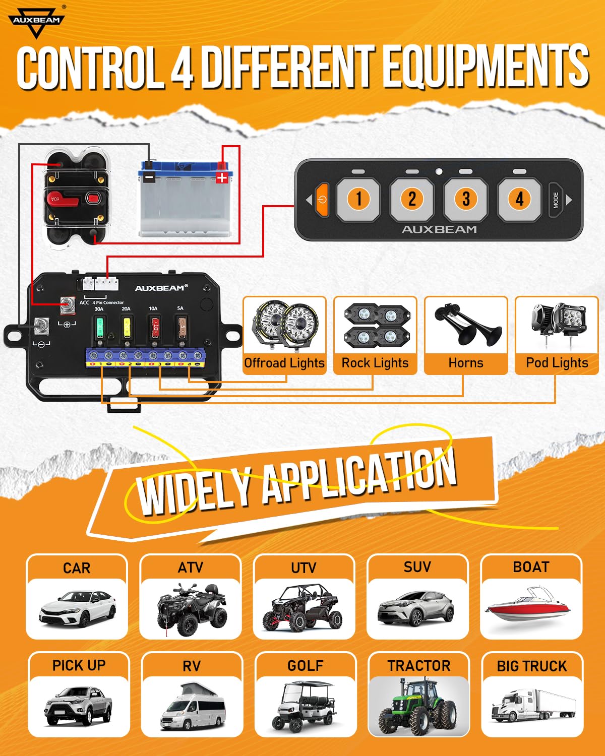
Image: A collage of different vehicle types, such as cars, ATVs, UTVs, SUVs, boats, pickups, RVs, golf carts, tractors, and big trucks, demonstrating the wide range of applications for the switch panel.
5. Setup and Installation
Proper installation is key to the optimal performance and longevity of your Auxbeam AS-R40 switch panel. Follow these steps carefully:
5.1 Choosing an Installation Location
The switch panel can be mounted or adhered using the provided double-sided tape in various locations within your vehicle, such as the dash panel, center console, or overhead sunglasses holder. Consider accessibility and visibility when selecting a spot.

Image: Depiction of two primary installation methods: using mounting brackets or double-sided tape, with examples of the panel installed in various vehicle interiors.
5.2 Wiring Connection
The system is designed to simplify wiring by consolidating connections through the circuit control box. This helps to reduce wire clutter in the engine bay.

Image: A simplified wiring diagram showing how the Auxbeam switch panel and circuit control box connect to the vehicle's battery and various auxiliary devices, indicating circuit capacities.
- Connect the main power cables from the circuit control box directly to your vehicle's battery (positive and negative terminals).
- Connect your auxiliary lights or electrical devices to the designated output terminals on the circuit control box. Each circuit has a specific amperage rating (Circuit 1: 30A, Circuit 2: 20A, Circuit 3: 10A, Circuit 4: 5A).
- Ensure the 10ft wire harness connects the switch panel to the circuit control box securely.
- Utilize the provided labels to clearly identify each switch's function.

Image: A visual comparison showing a messy, tangled wiring setup in an engine bay (Before) versus a tidy and organized setup after installing the Auxbeam switch panel (After), highlighting improved safety and aesthetics.
6. Operating Instructions
The Auxbeam AS-R40 switch panel offers intuitive control over your connected accessories.
6.1 Basic Operation

Image: Close-up of the Auxbeam switch panel, with labels pointing to LED indicators, the automatic light sensor, ON/OFF button, ON/OFF button indicator, MODE button, and MODE button indicator.
- Power On/Off: Press the "ON/OFF" button to activate or deactivate the switch panel. The panel will remember your last settings upon reactivation.
- Activating Accessories: Press the individual switch buttons (1-4) to control the connected devices. An LED indicator above each button will illuminate when the circuit is active.
6.2 Changing Lighting Modes
Each switch can operate in one of three modes: TOGGLE, MOMENTARY, or PULSED. To change the mode for a specific switch:
- Ensure the switch panel is powered on.
- Press and hold the desired switch button for approximately 3 seconds until the mode changes.
- Repeat the process to cycle through the modes (TOGGLE → MOMENTARY → PULSED → TOGGLE).
6.3 Adjusting Backlight Brightness and Color
The AS-R40 features auto-dimming and allows for manual backlight control.

Image: Illustration showing two methods for adjusting backlight brightness: manually turning off the backlight with the MODE button, and automatic brightness adjustment based on ambient light.
- Auto-Dimming: The panel automatically adjusts its backlight brightness based on the surrounding light conditions. It brightens in bright environments and dims in dark environments.
- Manual Backlight OFF: Press the "MODE" button once to quickly deactivate the backlight. Press it again to reactivate.
- RGB Color Options: The panel offers countless RGB backlight color options. The specific method for cycling through colors is typically integrated with the "MODE" button or automatic sensing.
7. Maintenance
Regular maintenance ensures the longevity and optimal performance of your Auxbeam AS-R40 switch panel.
- Cleaning: Use a soft, damp cloth to clean the switch panel and control box. Avoid abrasive cleaners or solvents that could damage the surfaces.
- Protective Cover: The included silicone protective cover helps shield the switch panel from water, dust, and dirt. Ensure it is properly fitted, especially in harsh environments.
- Wiring Inspection: Periodically check all wiring connections for tightness and signs of wear or corrosion. Re-secure any loose connections.
- Circuit Breaker: The resettable circuit breaker is designed to protect the system. If it trips, investigate the cause (e.g., overcurrent, short circuit) before resetting.
- Sticker Replacement: The panel design allows for easy replacement of stickers. Gently pry open the sticker area with a sharp tool if you wish to change the labels.

Image: The silicone protective cover shown in various scenarios, illustrating its ability to prevent damage from splashing water, snowfall, wind, sand, and dirty hands, ensuring durability in diverse conditions.

Image: The Auxbeam switch panel displayed with the included 60-piece sticker set (55 default, 5 DIY), demonstrating how to easily replace stickers for customization.
8. Troubleshooting
If you encounter issues with your Auxbeam AS-R40 switch panel, refer to the following common problems and solutions:
| Problem | Possible Cause | Solution |
|---|---|---|
| Panel does not power on. | No power supply; loose connections; tripped circuit breaker. | Check battery connections. Ensure all wires are securely connected. Check and reset the circuit breaker. |
| Individual switch not working. | Loose accessory connection; faulty accessory; incorrect mode setting. | Verify the accessory is properly connected to the control box. Test the accessory directly if possible. Ensure the switch is in the desired mode (Toggle, Momentary, Pulsed). |
| Backlight not functioning or stuck. | Backlight OFF function activated; sensor obstruction. | Press the "MODE" button to toggle the backlight. Ensure the automatic light sensor is not obstructed. |
| System shuts down unexpectedly. | Overcurrent, overvoltage, or overheating detected. | The circuit breaker has tripped for protection. Disconnect accessories, allow system to cool, then reset the breaker. Reduce load or check for short circuits. |
9. Specifications
Key technical specifications for the Auxbeam AS-R40 Slim Switch Panel:
| Feature | Detail |
|---|---|
| Model | AS-R40 (WITHOUT APP) |
| Operation Mode | Manual |
| Operating Voltage | 12-24 Volts (DC) |
| Maximum Power | 720W (12V) / 1400W (24V) |
| Maximum Current | 60A |
| Circuit Type | 4-way |
| Number of Positions | 4 |
| Contact Type | Normally Open |
| Actuator Type | Push Button |
| Contact Material | Copper |
| Operating Temperature | -40°F to 221°F (-40°C to 105°C) |
| Package Dimensions | 13.07 x 8.86 x 4.37 inches |
| Weight | 4.81 Pounds |

Image: Detailed specifications of the circuit box, including maximum current (60A), input voltage (DC 12-24V), maximum power (720W/12V, 1400W/24V), and operating temperature range (-40°F to 221°F).
10. Warranty and Support
Auxbeam provides a 2-year warranty for the AS-R40 Slim Switch Panel, covering manufacturing defects and malfunctions under normal use. For warranty claims, technical assistance, or any product-related inquiries, please contact Auxbeam customer support through their official channels or the retailer where the product was purchased.
For more information and support, visit the official Auxbeam store: Auxbeam Store on Amazon.
Ask a question about this manual
Ask about setup, troubleshooting, compatibility, parts, safety, or missing instructions. Manuals+ will review the question and use this page’s manual context to help answer it.