1. Introduction
This manual provides essential information for the safe and efficient operation of your PowMr 10000W Split Phase Solar Inverter. This low-frequency pure sine wave inverter is designed for off-grid home backup power, featuring a built-in 120A MPPT controller and a 105A AC charger. It supports both solar and AC input, providing reliable 120V/240V output from a 48V battery system.
Please read this manual thoroughly before installation and use, and retain it for future reference.
2. Safety Instructions
Adherence to these safety guidelines is crucial to prevent personal injury and damage to the inverter or connected equipment.
- Electrical Safety: Installation and maintenance must be performed by qualified personnel. Ensure all power sources are disconnected before working on the inverter.
- Ventilation: Install the inverter in a well-ventilated area to prevent overheating. Maintain adequate clearance around the unit.
- Environment: Avoid exposure to water, moisture, direct sunlight, and flammable materials. Operate within specified temperature and humidity ranges.
- Grounding: The inverter must be properly grounded. Ensure the protective earth conductor is connected first.
- Battery Safety: Work with batteries carefully. Wear protective eyewear. Do not short-circuit battery terminals.
- Overload Protection: Do not exceed the inverter's rated power capacity.
3. Product Overview
The PowMr 10000W Split Phase Solar Inverter is a robust low-frequency unit designed for stable and reliable power conversion. Its key features include a large toroidal transformer for enhanced surge capacity and durability, a 120A MPPT solar charge controller, and a 105A AC charger.
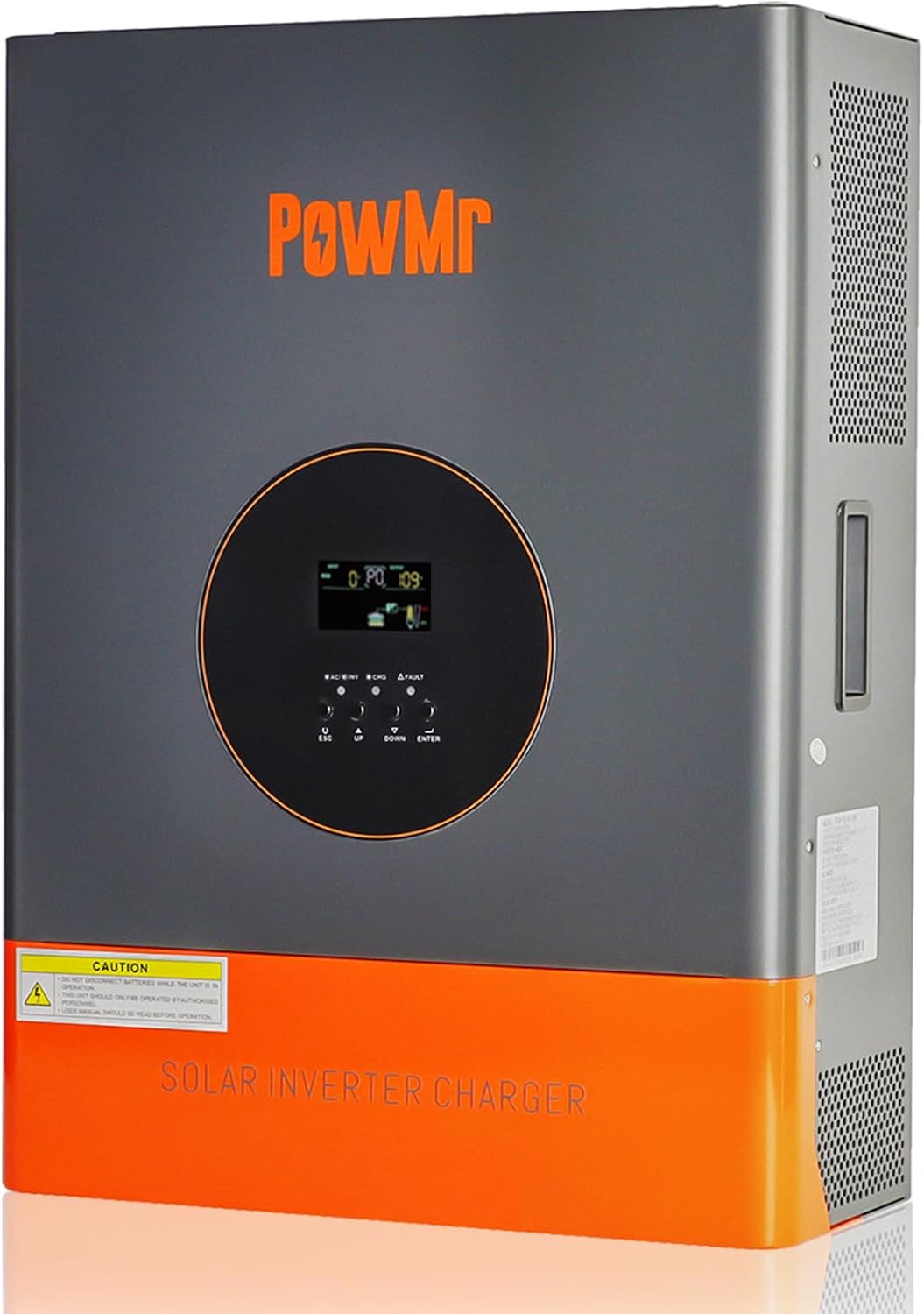
Figure 3.1: Front view of the PowMr 10000W Split Phase Solar Inverter, showing the display and control buttons.
3.1 Key Features
- Low-Frequency Design: Utilizes a large toroidal transformer for superior reliability, stability, and enhanced surge power capacity (30000W peak).
- Integrated MPPT Controller: Built-in 120A MPPT solar charge controller for efficient solar energy harvesting.
- AC Charger: Features a 105A AC charger for utility or generator charging.
- Battery Compatibility: Supports various battery types including LiFePO4, Lead-Acid (AGM, GEL, FLD, SLD), and user-defined settings.
- Split-Phase Output: Provides 120V/240V split-phase output for a wide range of household and office loads.
- Comprehensive Protections: Includes multiple built-in protection functions and precise alarm mechanisms for system safety.
- UPS Functionality: Ultra-fast 10ms UPS ensures uninterrupted operation during power transitions.

Figure 3.2: Overview of the inverter's key specifications and features, including 10KW AC output, 30KW peak power, and 120A max PV charging.
3.2 Component Identification
Refer to the diagram below for identification of the inverter's external components and connection terminals.

Figure 3.3: Diagram illustrating the location of the LCD screen, LED indicators, LCD buttons, toggle switch, AC input/output terminals, PV input terminal, communication port, and battery circuit fuse.
4. Setup and Installation
Proper installation is critical for the safe and optimal performance of your inverter. Follow these steps carefully.
4.1 Mounting the Inverter
- Choose a dry, cool, and well-ventilated location.
- Ensure the mounting surface is strong enough to support the inverter's weight (approximately 129 pounds).
- Allow sufficient clearance around the unit for airflow.
4.2 Wiring Connections
All wiring must comply with local electrical codes and standards. Use appropriate wire gauges for all connections.

Figure 4.1: Detailed wiring diagram showing connections for solar panels, battery, AC input (utility/generator), and AC output to loads. Includes technical specifications for each connection point.
- Grounding: Connect the ground wire first to the inverter's ground terminal and then to a reliable earth ground.
- Battery Connection: Connect the 48V battery bank to the inverter's battery terminals. Ensure correct polarity (positive to positive, negative to negative). The battery must be connected for the inverter to operate. Recommended battery capacity is 200 Amp Hours.
- PV Input Connection: Connect your solar panels to the PV input terminals. Ensure the maximum PV input power (6400W) and voltage (150V VOC) are not exceeded. Starting voltage must be greater than 60V.
- AC Input Connection: Connect the utility grid or a generator to the AC input terminals. The AC input voltage is 120Vac±5% (50Hz/60Hz).
- AC Output Connection: Connect your household or office loads to the AC output terminals. The inverter provides 10000W continuous AC output power.
4.3 Battery Type Selection
The inverter is compatible with various 48V battery types. Select the appropriate battery type in the inverter's settings menu for optimal charging and discharge performance.
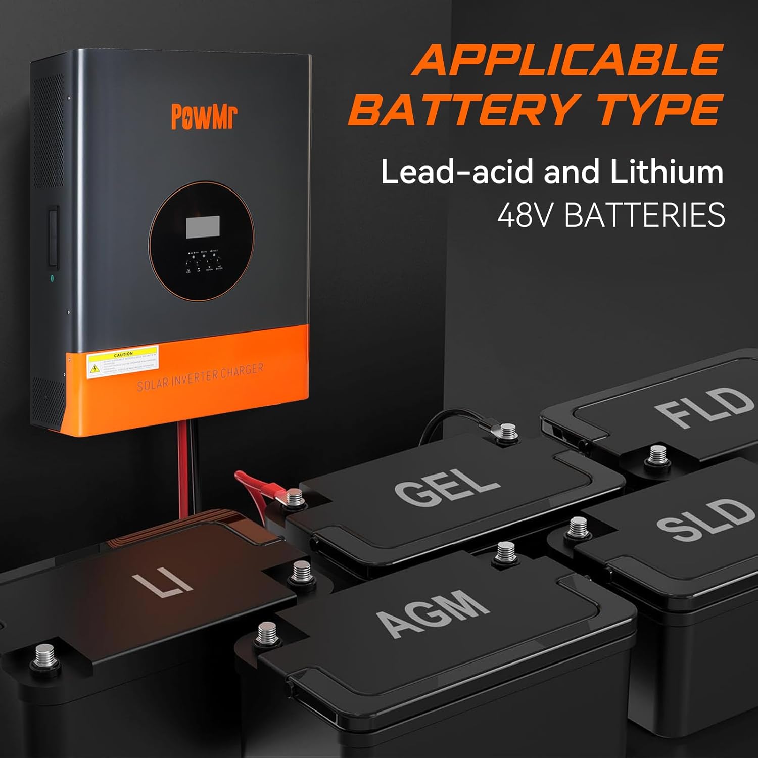
Figure 4.2: Illustration showing the inverter's compatibility with various 48V battery types, including Lead-acid (AGM, GEL, FLD, SLD) and Lithium (LiFePO4).
5. Operating the Inverter
Once installed, the inverter offers flexible operating modes to suit your energy needs.
5.1 Powering On/Off
- To Power On: Ensure all connections are secure. Switch on the battery breaker, then the AC input breaker (if applicable), and finally the inverter's power switch.
- To Power Off: Reverse the power-on sequence: inverter switch off, then AC input breaker off, and finally battery breaker off.
5.2 Charging Modes
The inverter supports three battery charging modes, configurable via the LCD display:

Figure 5.1: Visual representation of the three battery charging modes (Utility Priority, Solar Priority, Only Solar) and three load output modes (Utility Priority, Solar Priority, Inverter Priority).
- Utility Priority: The inverter primarily uses utility power to charge the battery. Solar power acts as a supplementary charging source.
- Solar Priority: Solar power is the primary source for battery charging. Utility power is used only when solar power is insufficient.
- Only Solar: Only solar power is used to charge the battery. Utility power is not used for charging.
5.3 Output Modes
The inverter also offers three load output working modes:
- Utility Priority: Loads are primarily supplied by utility power. If utility power fails, the inverter switches to battery power.
- Solar Priority: Loads are primarily supplied by solar power. If solar power is insufficient, the inverter switches to battery power. If both solar and battery are insufficient, utility power is used (if available).
- Inverter Priority: Loads are primarily supplied by the inverter from battery power. Utility power is used only when the battery voltage drops to a low warning level.
5.4 LCD Display and Controls
The LCD display provides real-time operational status, battery voltage, charging current, and output power. Use the navigation buttons (UP, DOWN, ENTER, ESC) to browse menus and adjust settings.
6. Maintenance
Regular maintenance ensures the longevity and optimal performance of your inverter.
- Cleaning: Periodically clean the inverter's exterior with a dry cloth. Ensure ventilation openings are free from dust and debris.
- Connection Checks: Annually inspect all electrical connections (battery, solar, AC input/output) for tightness and corrosion. Tighten any loose connections.
- Battery Inspection: Regularly check battery terminals for corrosion and ensure battery fluid levels (for flooded lead-acid batteries) are adequate.
- Firmware Updates: Check the manufacturer's website for any available firmware updates.
7. Troubleshooting
This section addresses common issues you might encounter. For problems not listed here, contact technical support.
| Problem | Possible Cause | Solution |
|---|---|---|
| Inverter does not power on | No battery connection; Low battery voltage; Blown fuse | Check battery connections; Charge battery; Check battery circuit fuse. |
| No AC output | Overload; Over-temperature; Output breaker tripped | Reduce load; Allow inverter to cool; Reset output breaker. |
| Solar charging not working | PV input voltage too low/high; Incorrect PV connection; MPPT controller fault | Check PV array voltage; Verify PV wiring polarity; Consult technical support. |
| Incorrect 220V split-phase output | Incorrect wiring hook-up | Carefully re-check the wiring diagram and use a voltmeter to confirm terminal connections for 120V/240V output. Ensure L1, L2, and Neutral are correctly identified and connected. |
8. Technical Specifications
| Feature | Specification |
|---|---|
| Model Number | Temank-10000W-48V |
| AC Output Power | 10000W |
| Peak Power | 30000W |
| Battery Voltage | 48V |
| AC Output Voltage | 120V/240V (Split-Phase) |
| Max PV Input Power | 6400W |
| Max PV Input Voltage (VOC) | 150V |
| Max PV Output Current | 120A (MPPT Controller) |
| AC Charger Current | 105A |
| Hybrid Charging Max Current | 120A (AC charger + PV charger) |
| Starting Voltage | >60V |
| UPS Transfer Time | 10ms |
| Recommended Battery Capacity | 200 Amp Hours |
| Item Weight | 129 pounds |
| Package Dimensions | 26 x 20 x 10 inches |
9. What's in the Box
Upon unpacking, please verify that all items listed below are included and undamaged.

Figure 9.1: Image showing the inverter unit and its included accessories.
- PowMr 10000W Low-Frequency Solar Inverter Unit
- Communication Cable (RS-232/RS-422)
- Mounting Bracket and Hardware
- User Manual (this document)
10. Warranty and Support
Your PowMr 10000W Split Phase Solar Inverter is covered by a manufacturer's warranty. Please refer to the warranty card included in your package for specific terms and conditions, including warranty duration and coverage details.
For technical assistance, troubleshooting, or warranty claims, please contact Temank customer support through the retailer where the product was purchased or visit the official Temank website for contact information.
Manufacturer: Temank
Date First Available: June 27, 2024


