1. Product Overview
The GEYA GRT6-M1 Multifunctional Delay Time Relay is a versatile device designed for precise timing control in various electrical applications. It offers 10 distinct time functions and 10 time ranges, making it suitable for controlling lights, heating systems, motors, pumps, and fans. Its compact design allows for easy DIN rail mounting.
Key Features:
- Widespread Use: Ideal for electrical appliances, control of lights, heating, motors, pumps, and fans.
- 10 Function Choices: Includes 5 time functions controlled by supply voltage, 4 time functions controlled by control input, and 1 function of latching relay.
- Adjustable Time Ranges: Time scale from 0.1 seconds to 10 days, divided into 10 ranges for precise setting.
- Compact Size: Ultra-small dimensions (18mm x 64mm x 90mm) for 35mm DIN rail mounting.
- Relay Status Indication: LED indicators clearly display the working status of the relay.
2. Technical Specifications
| Parameter | GRT6-M1 |
|---|---|
| Function | A, B, C, D, E, F, G, H, I, J |
| Supply Terminals | A1-A2 |
| Voltage Range | AC/DC 24V-240V (50-60Hz) |
| Burden | AC 0.09-3VA/DC 0.05-1.7W |
| Time Ranges | 0.1s-10days, ON, OFF |
| Time Setting | Potentiometer |
| Time Deviation | 10% mechanical setting |
| Repeat Accuracy | 0.2% set value stability |
| Temperature Coefficient | 0.05%/°C, at 20°C (0.05%°F, at 68°F) |
| Output | 1 x SPDT |
| Current Rating | 10A / AC1 |
| Switching Voltage | 250VAC / 24VDC |
| Min. Breaking Capacity | 500mW |
| Output Indication | Red LED |
| Mechanical Life | 1 x 10⁷ |
| Electrical Life (AC1) | 1 x 10⁵ |
| Reset Time | Max. 200ms |
| Operating Temperature | -20°C to +55°C (-4°F to 131°F) |
| Storage Temperature | -35°C to +75°C (-22°F to 158°F) |
| Mounting/DIN Rail | DIN rail EN/IEC 60715 |
| Protection Degree | IP40 for front panel / IP20 terminals |
| Operating Position | Any |
| Overvoltage Category | III |
| Pollution Degree | 2 |
| Max. Cable Size (mm2) | Solid wire max. 1 x 2.5 or 2 x 1.5 with sleeve max. 1 x 2.5 (AWG 12) |
| Tightening Torque | 0.4Nm |
| Dimensions | 90 x 18 x 64mm |
| Weight | 1 x SPDT: S240-63g, A230-62g |
| Standards | EN 61812-1, IEC60947-5-1 |
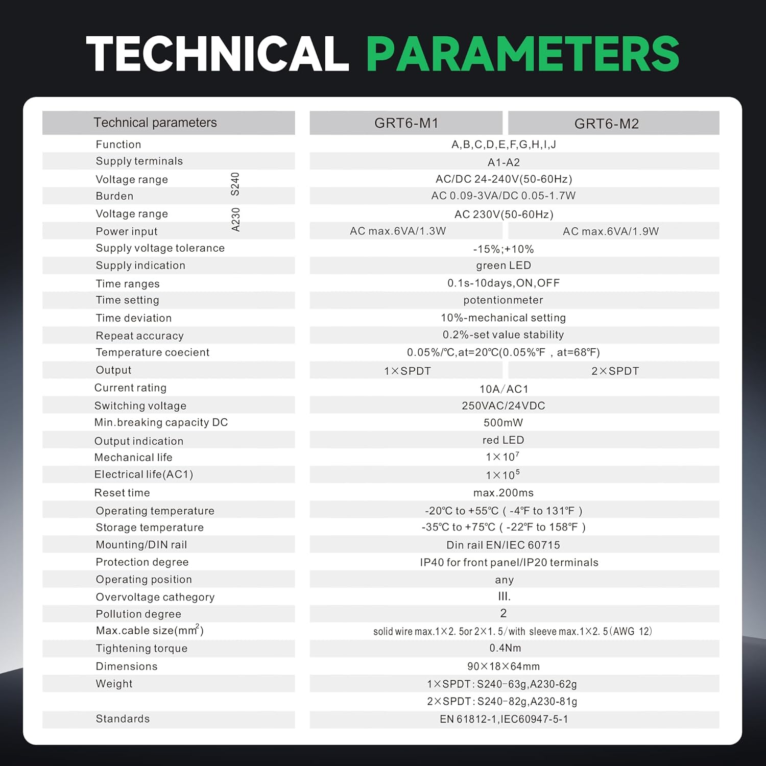
Image: Detailed technical specifications for GRT6-M1 and GRT6-M2 models, including functions, supply voltage, time ranges, and environmental conditions.
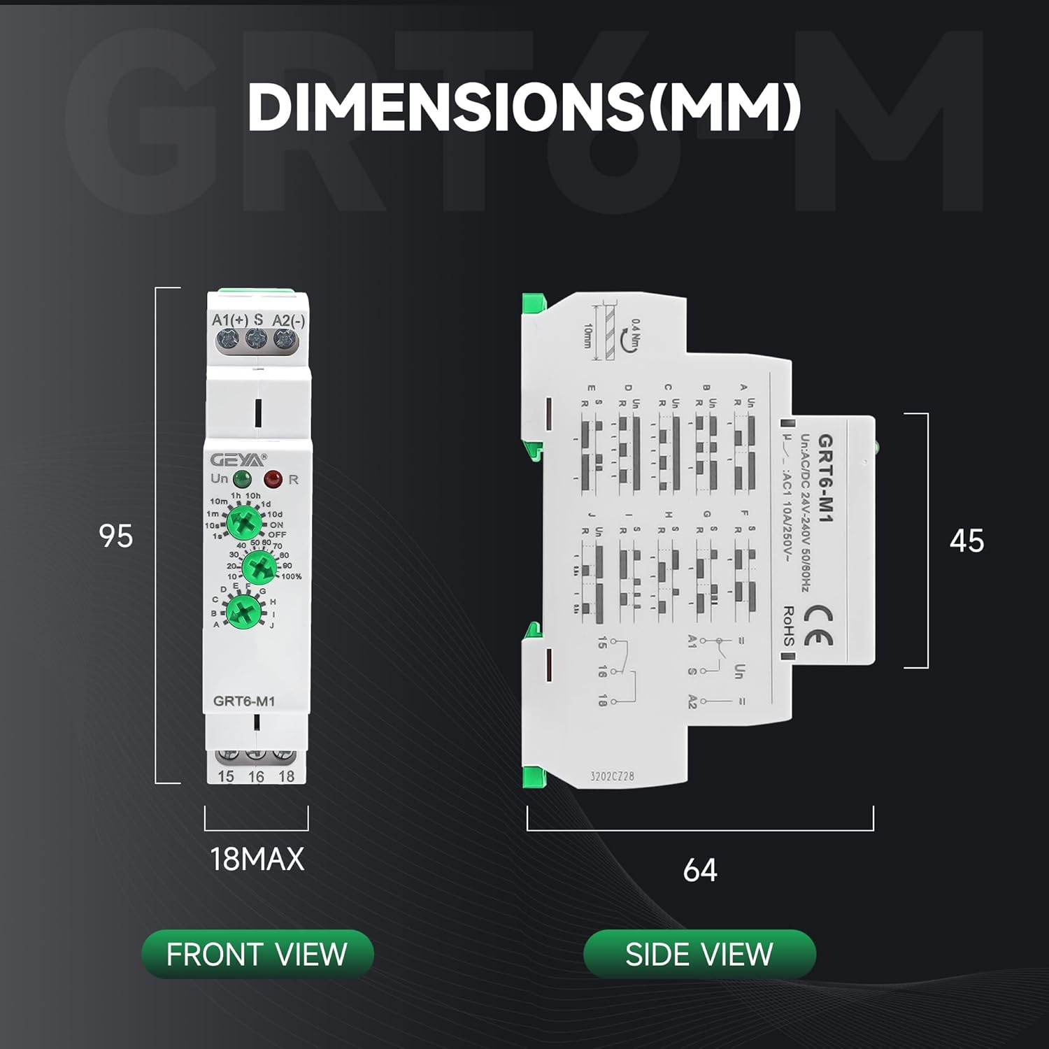
Image: Front and side views illustrating the dimensions of the GRT6-M1 relay in millimeters (95mm height, 18mm max width, 64mm depth).
3. Installation and Wiring
The GEYA GRT6-M1 relay is designed for 35mm DIN rail mounting. Ensure all power is disconnected before installation or wiring.
Wiring Diagram:
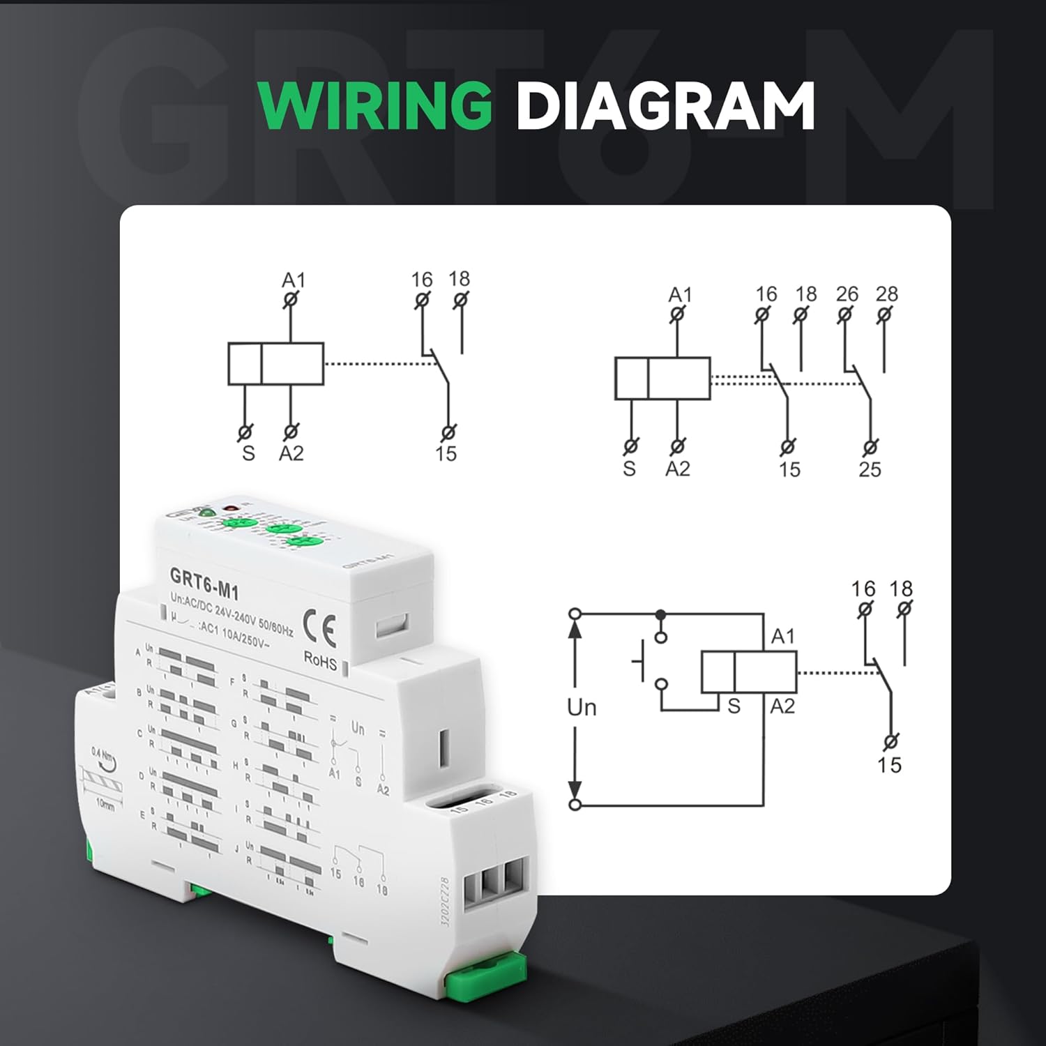
Image: A detailed wiring diagram showing connections for terminals A1, S, A2, 15, 16, and 18, illustrating typical circuit configurations for the GRT6-M1 relay.
Connection Usage:
Video: Demonstrates the physical connection process for the GRT6 series relay, showing how to wire it to a power supply and a load.
4. Operating Instructions
The GRT6-M1 relay features three rotary knobs for setting time range, time percentage, and function mode. Refer to the diagrams and videos below for specific mode operations.
Setting Time and Function:
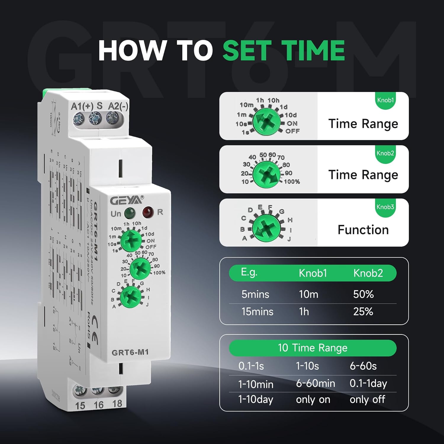
Image: Illustrates the three knobs (Knob1 for Time Range, Knob2 for Time Percentage, Knob3 for Function) and provides examples of time settings.

Image: Displays the 10 different delay modes (A-J) available on the GRT6-M1 relay, categorized by control type (power supply voltage or control input).
Function Mode Demonstrations:
Mode A: On Delay (Power On)
In Mode A, the load is controlled by the power supply. After power is applied, the relay delays for the set time before connecting the load. When power is removed, the load immediately disconnects.
Video: Demonstrates the operation of GRT6-M1 in Mode A (On Delay). The light flashes during the set delay time and then turns on, remaining on until power is cut.
Mode B: Interval (Power On)
In Mode B, the load is connected immediately upon power-on and remains connected for the set delay time, after which it disconnects. This mode is controlled by the supply voltage.
Video: Illustrates the functionality of GRT6-M1 in Mode B (Interval). The load activates immediately upon power-on and then deactivates after the set time.
Mode C: Repeat Cycle (Starting Off)
Mode C initiates a repeating cycle where the load remains off for the set delay time, then turns on for the same duration, and repeats. This cycle starts with the load off.
Video: Shows the GRT6-M1 operating in Mode C (Repeat Cycle, Starting Off). The load cycles on and off with the set delay, beginning with an off period.
Mode E: Off Delay (Trigger Switch Break)
In Mode E, the load is not connected until a trigger button is pressed. Once the button is released, a delay begins, and the load disconnects after the set time. If the load is reconnected during timing, the timing delay is cut out and restarts.
Video: Demonstrates GRT6-M1 in Mode E (Off Delay). The load activates when a button is pressed and released, then deactivates after a set delay. Re-triggering resets the delay.
Mode F: Single Shot (Triggered by Signal)
Mode F is a single shot function. When a trigger signal is applied, the load immediately connects and remains on for the set delay time, then disconnects. Pressing the button during the delay does not affect the timing.
Video: Illustrates the GRT6-M1 in Mode F (Single Shot). The load activates for a set duration upon a trigger signal and then turns off, ignoring further triggers during the active period.
Mode G: Single Shot Trailing Edge (Non-Retriggerable)
In Mode G, the load is not connected until the trigger signal is released (trailing edge). Once released, the load connects for the set delay time and then disconnects. Pressing the button during the delay does not affect the timing.
Video: Demonstrates GRT6-M1 in Mode G (Single Shot Trailing Edge). The load activates for a set duration when the trigger button is released, then turns off, ignoring further triggers during the active period.
Mode H: On/Off Delay
Mode H provides both on and off delay functionality controlled by a signal. When the trigger button is held down, the load connects after an initial delay. When the button is released, the load disconnects after a second delay.
Video: Shows the GRT6-M1 operating in Mode H (On/Off Delay). The load turns on after a delay when the button is pressed and turns off after a delay when the button is released.
Mode I: Latching Relay
Mode I functions as a latching relay. Each press of the trigger button toggles the state of the load (on/off). There is no delay function in this mode.
Video: Demonstrates GRT6-M1 in Mode I (Latching Relay). Each press of the trigger button toggles the state of the connected load (on or off) without any timing delay.
Mode J: Pulse Generator
In Mode J, the relay acts as a pulse generator. Upon power-on, the load immediately connects for a very short duration (0.5 seconds) and then disconnects. This mode is delayed by power-on.
Video: Shows the GRT6-M1 operating in Mode J (Pulse Generator). Upon power-on, the load briefly activates for 0.5 seconds and then deactivates.
5. Maintenance and Care
The GEYA GRT6-M1 relay is designed for durability and requires minimal maintenance. Ensure the device is kept clean and free from dust and moisture. Periodically check terminal connections for tightness to prevent electrical issues. The flame-retardant material shell provides enhanced safety.
6. Troubleshooting
If the relay is not functioning as expected, consider the following:
- No Power/LED Off: Check the power supply connections and ensure the correct voltage (AC/DC24V-240V) is applied. Verify circuit breakers are on.
- Incorrect Timing/Function: Re-check the settings of the three rotary knobs (Time Range, Time Percentage, Function Mode) according to the desired operation.
- Load Not Activating: Inspect the wiring to the load and ensure it is correctly connected to terminals 15, 16, and 18. Confirm the load itself is functional.
- Intermittent Operation: Ensure all wire connections are secure and tightened to 0.4Nm. Check for any loose wiring or damaged insulation.
- Signal Input Issues: For modes controlled by external input (S terminal), verify the trigger button or sensor is correctly wired and functioning.
If issues persist, consult a qualified electrician or contact GEYA customer support.
7. Warranty and Support
GEYA products are manufactured to high-quality standards. For warranty information or technical support, please refer to the official GEYA website or contact your local distributor. Keep your purchase receipt for warranty claims.


