1. Introduction
This manual provides essential information for the proper installation, operation, and maintenance of your WELURE SEN01114 Flame Sensor Rod. Please read these instructions carefully before attempting any installation or service. Proper understanding and adherence to these guidelines will ensure safe and efficient operation of your furnace.
The flame sensor is a critical safety component in your furnace system. It is designed to detect the presence of a flame in the burner assembly. If a flame is not detected when the gas valve is open, the sensor signals the furnace control board to shut off the gas supply, preventing uncombusted gas from accumulating and creating a hazardous condition.
2. Product Overview
The WELURE SEN01114 Flame Sensor Rod is a replacement part compatible with various American Standard and Trane residential furnace models. It is constructed from high-quality, durable materials designed to withstand the high temperatures and operational demands of a furnace environment.

Figure 2.1: Two WELURE SEN01114 Flame Sensor Rods. These rods are designed to detect the presence of a flame in your furnace.
2.1 Key Features
- Function: Monitors the burner to detect flame presence by sending a DC current through the sensor via the flame itself.
- Material: Made from advanced materials to prevent cracking and damage during installation and use, ensuring durability.
- Compatibility: Direct replacement for many American Standard and Trane residential furnace models.
- Package Contents: Each package includes two (2) SEN01114 Flame Sensor Rods.
3. Compatibility
The WELURE SEN01114 Flame Sensor Rod is a direct replacement for the following part numbers: SEN337, SEN0337, SEN441, SEN0441, SEN491, SEN00491, SEN1114, PSE-T19, B340888-2.
It is compatible with a wide range of American Standard and Trane furnace models. A partial list of compatible models includes:
- ADC1B040A9241AA, ADC1B040A9241AB, ADC1B040A9241AC, ADC1B040A9241AD
- ADC1B060A9361AA, ADC1B060A9361AB, ADC1B060A9361AC, ADC1B060A9361AD
- ADC1B080A9421AA, ADC1B080A9421AB, ADC1B080A9421AC, ADC1B080A9421AD, ADC1B080A9421AE
- ADC1C100A9481AA, ADC1C100A9481AB, ADC1C100A9481AC, ADC1C100A9481AD
- ADC1D120A9601AA, ADC1D120A9601AB, ADC1D120A9601AC, ADC1D120A9601AD
- ADD1A040A9241AA, ADD1A040A9241AB, ADD1A060A9241AA, ADD1A060A9241AB
- ADD1A060A9361AA, ADD1A060A9361AB, ADD1B060A9361AA, ADD1B060A9361AB
- ADD1B060A9H31AA, ADD1B060A9H31BA, ADD1B060A9H31BB
- ADD1B080A9361AA, ADD1B080A9361AB, ADD1B080A9451AA, ADD1B080A9451AB
- ADD1B080A9H31AA, ADD1B080A9H31BA, ADD1B080A9H31BB
- ADD1B100A9451AA, ADD1B100A9451AB
- ADD1C100A9481AA, ADD1C100A9481AB, ADD1C100A9541AA, ADD1C100A9541AB
- ADD1C100A9H51AA, ADD1C100A9H51BA, ADD1C100A9H51BB
- ADD1C120A9541AA, ADD1C120A9541AB, ADD1D120A9601AA, ADD1D120A9601AB
- ADD1D120A9H51AA, ADD1D120A9H51BA, ADD1D120A9H51BB, ADD1D140A9601AA
- ADD2B060ACV32AA, ADD2B060ACV32AB, ADD2B080ACV32AA, ADD2B080ACV32AB
- ADD2C100ACV52AA, ADD2C100ACV52AB, ADD2D120ACV52AA, ADD2D120ACV52AB
- ADE1A060A9361AA, ADE1A060A9361AB, ADE1B060A9361AA, ADE1B060A9361AB
- ADE1B080A9451AA, ADE1B080A9451AB, ADE1B100A9451AA, ADE1B100A9451AB
- ADE1C100A9601AA, ADE1C100A9601AB, ADE1D120A9601AA, ADE1D120A9601AB
- ADH1B040A9241AA, ADH1B065A9421AA, ADH1C085A9481AA, ADH1D110A9601AA
- ADH2B060A9V3VAA, ADH2B060A9V3VAB, ADH2B060A9V3VAC, ADH2B060A9V3VAD
- ADH2B080A9V3VAA, ADH2B080A9V3VAB, ADH2B080A9V3VAC, ADH2B080A9V3VAD
- ADH2B080A9V4VAC, ADH2C100A9V4VAA, ADH2C100A9V4VAB, ADH2C100A9V4VAC
- ADH2C100A9V4VAD, ADH2D120A9V5VAA, ADH2D120A9V5VAB, ADH2D120A9V5VAC
- ADH2D120A9V5VAD, AUE1A060A9361AC, AUE1B060A9361AA, AUE1B060A9361AB
- AUE1B060A9361AC, AUE1B080A9361AA, AUE1B080A9361AB, AUE1B080A9361AC
- AUE1B080A9481AA, AUE1B080A9481AB, AUE1B080A9481AC
- AUE1B100A9361AA, AUE1B100A9361AB, AUE1B100A9361AC
- AUE1C100A9481AA, AUE1C100A9481AB
Please verify your furnace model number against the complete compatibility list provided on the product's retail page or consult your furnace manufacturer's documentation to ensure proper fitment.
4. Safety Information
WARNING: Installation and service of furnace components should only be performed by qualified personnel. Improper installation, adjustment, alteration, service, or maintenance can cause property damage, personal injury, or loss of life.
- Always disconnect the electrical power to the furnace before performing any service or maintenance.
- Turn off the gas supply to the furnace before beginning any work.
- Wear appropriate personal protective equipment (PPE), such as gloves and eye protection.
- Ensure the work area is well-ventilated.
- Never bypass safety devices.
5. Installation
The WELURE SEN01114 Flame Sensor Rod is designed for simple replacement. Follow these steps carefully:
- Power Disconnection: Locate the main power switch for your furnace and turn it OFF. Additionally, turn off the gas supply valve to the furnace.
- Access the Burner Area: Open the furnace access panel to expose the burner assembly and existing flame sensor.
- Locate Old Sensor: Identify the current flame sensor. It is typically a single metal rod with a ceramic insulator, positioned in the path of the burner flame.
- Remove Old Sensor: Carefully disconnect the wire leading to the old flame sensor. Using a wrench or socket, unbolt the old sensor from its mounting bracket.
- Install New Sensor: Position the new WELURE SEN01114 Flame Sensor Rod in the same location and orientation as the old one. Secure it with the mounting bolt.
- Connect Wiring: Reconnect the wire to the terminal on the new flame sensor. Ensure the connection is secure.
- Close Access Panel: Replace the furnace access panel.
- Restore Power: Turn the gas supply valve back ON. Restore electrical power to the furnace.
- Test Operation: Initiate a heating cycle on your thermostat to test the furnace operation. Observe the burner ignition and ensure the flame remains lit.

Figure 5.1: Illustration of flame sensor installation and furnace flame states. The installation process involves removing the old sensor, connecting the new one, and restarting the power supply.
6. Operation
Once installed, the WELURE SEN01114 Flame Sensor Rod operates automatically as part of your furnace's safety system. When the furnace calls for heat:
- The igniter activates, and the gas valve opens to supply fuel to the burners.
- As the burners ignite, the flame sensor, positioned within the flame path, detects the presence of the flame.
- The sensor sends a small electrical current (rectified AC current, often referred to as DC current in this context) through the flame to the furnace control board.
- If the control board receives this signal, it confirms that a flame is present and allows the gas valve to remain open, continuing the heating cycle.
- If the flame sensor does not detect a flame within a specified timeframe (e.g., due to ignition failure or flame loss), the control board will immediately close the gas valve, preventing unburned gas from entering your home. This safety mechanism is crucial for preventing gas leaks and potential explosions.
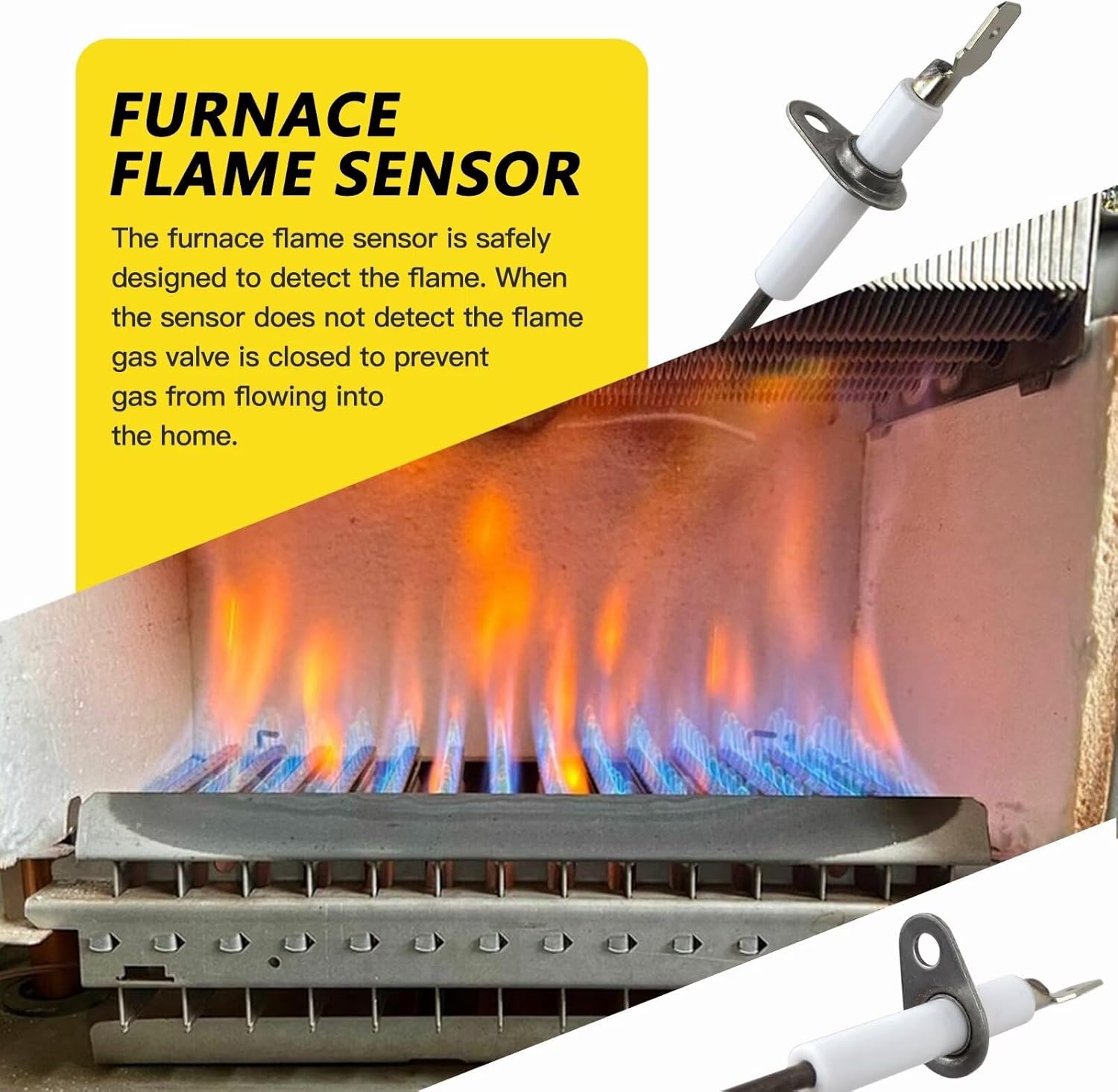
Figure 6.1: A flame sensor positioned within a furnace burner assembly, detecting the flame. The sensor's primary role is to ensure the safe operation of the furnace by confirming flame presence.
7. Maintenance
Regular maintenance of your flame sensor can help prevent common furnace issues and ensure its longevity. It is recommended to inspect and clean the flame sensor annually, preferably before the heating season begins.
7.1 Cleaning the Flame Sensor
- Power Disconnection: Always turn off the electrical power and gas supply to the furnace before beginning any maintenance.
- Access and Remove: Follow steps 2-4 from the Installation section to access and carefully remove the flame sensor.
- Inspect: Examine the ceramic insulator and the metal rod for any signs of cracks, damage, or excessive carbon buildup. A thin layer of carbon or oxidation can interfere with the sensor's ability to detect the flame.
- Clean: Gently clean the metal rod using fine-grit sandpaper (e.g., 180-grit or finer) or a Scotch-Brite pad. Do not use steel wool, as it can leave behind conductive particles. The goal is to remove any carbon or oxidation without scratching the rod excessively. Avoid bending the rod or damaging the ceramic insulator.
- Reinstall: Reinstall the cleaned flame sensor by following steps 5-8 from the Installation section.
- Test: Restore power and gas, then test the furnace operation to ensure the sensor is functioning correctly.
8. Troubleshooting
A malfunctioning flame sensor is a common cause of furnace issues. If your furnace is experiencing problems related to ignition or frequent shutdowns, consider the following:
8.1 Common Symptoms of a Faulty Flame Sensor
- Furnace ignites, runs for a few seconds, then shuts off (short cycling).
- Furnace attempts to ignite multiple times but fails to establish a flame.
- Furnace produces a clicking sound (from the igniter) but no flame appears.
- Furnace displays an error code related to flame sensing (consult your furnace manual for specific codes).

Figure 8.1: The WELURE SEN01114 Flame Sensor can help resolve issues such as frequent furnace stalling, quick engine shutdown after starting, and ensuring the furnace stays on once it fires up.
8.2 Troubleshooting Steps
- Inspect and Clean: First, attempt to clean the flame sensor as described in the Maintenance section. Often, a dirty sensor is the cause of intermittent flame detection.
- Check Wiring: Ensure the wire connected to the flame sensor is secure and free from damage or corrosion.
- Verify Grounding: A proper ground connection for the furnace is essential for the flame sensor circuit to function correctly.
- Replace Sensor: If cleaning and checking connections do not resolve the issue, the flame sensor may be faulty and require replacement. Use the WELURE SEN01114 Flame Sensor Rod as a direct replacement.
- Consult a Professional: If problems persist after replacing the flame sensor, it may indicate a more complex issue with the furnace control board, gas valve, or igniter. In such cases, it is strongly recommended to contact a qualified HVAC technician.
9. Specifications
| Attribute | Detail |
|---|---|
| Model Number | SEN01114 |
| Manufacturer | WELURE |
| Replaces Part Numbers | SEN337, SEN0337, SEN441, SEN0441, SEN491, SEN00491, SEN1114, PSE-T19, B340888-2 |
| Compatibility | Various American Standard and Trane residential furnace models |
| Package Quantity | 2 Flame Sensor Rods |
| Material | High-quality, durable materials |

Figure 9.1: Detailed dimensions of the WELURE SEN01114 Flame Sensor Rod. Key measurements include a 0.25-inch wide terminal, 0.7-inch terminal length, 1.5-inch total ceramic length, 0.85-inch ceramic body length, 0.3-inch ceramic diameter, 2.1-inch rod length, 1.2-inch bend height, and 0.17-inch rod diameter.
10. Warranty and Support
Specific warranty information for the WELURE SEN01114 Flame Sensor Rod is not provided in this manual. Please refer to the product's original purchase documentation or contact the seller directly for details regarding warranty coverage and customer support.