1. Introduction
This manual provides essential information for the safe and efficient installation, operation, and maintenance of your ATO 1 hp (0.75kW) 3 Phase AC Induction Motor. Please read this manual thoroughly before using the product and retain it for future reference.
The ATO 1 hp (0.75kW) 3 Phase AC Induction Motor is designed for various general-purpose machinery applications, including fans, pumps, compressors, machine tools, gearboxes, and transportation systems. It features high efficiency, robust construction, and reliable performance.
2. Product Overview
2.1 Key Features
- High Efficiency: Operates at 1 hp (0.75kW) with 1390 rpm, optimizing energy consumption and operational efficiency.
- Durable Construction: Features F insulation class and high-temperature resistant pure copper coils for safe and extended operation.
- Efficient Cooling: Equipped with heat dissipation holes and a totally enclosed fan-cooled (TEFC) design to prevent overheating and prolong service life.
- Compact Design: Suitable for various applications without requiring excessive space.
- Low Noise Operation: Designed to provide a quieter working environment.
- Easy Installation: High-quality base plate with pre-drilled holes simplifies mounting.
2.2 Components
The following diagram illustrates the main components of the ATO AC Induction Motor:

Figure 1: Motor Components Overview
This image displays the internal and external components of the motor, highlighting the rotor, junction box, heat dissipation system, copper coils, cold-rolled silicon sheet steel, and the fixed base for mounting.
- Rotor: The rotating part of the motor.
- Junction Box: Enclosure for electrical connections.
- Heat Dissipation System: Components designed to manage and release heat generated during operation.
- Copper Coils: Essential for electromagnetic induction.
- Cold-rolled Silicon Sheet Steel: Used in the motor's core for magnetic properties.
- Fixed Base: Provides stable mounting for the motor.
3. What's in the Box
Upon unpacking, please verify that all items listed below are present and undamaged:
- 1x ATO 3 Phase AC Induction Motor (Model: ATO-Y2-80M2-4)
If any components are missing or damaged, please contact your supplier immediately.
4. Specifications
The following table details the technical specifications of the ATO 1 hp (0.75kW) 3 Phase AC Induction Motor:
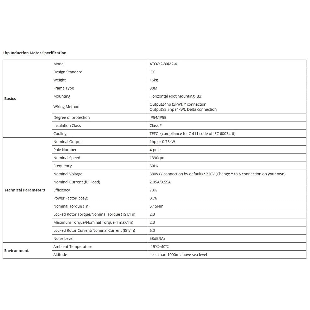
Figure 2: Technical Specifications
This image presents a detailed table outlining the motor's basic, technical, and environmental parameters.
| Category | Parameter | Value |
|---|---|---|
| Basics | Model | ATO-Y2-80M2-4 |
| Design Standard | IEC | |
| Weight | 15kg | |
| Frame Type | 80M | |
| Mounting | Horizontal Foot Mounting (B3) | |
| Wiring Method | Output≤4hp (3kW), Y connection Output≥5.5hp (4kW), Delta connection | |
| Technical Parameters | Degree of Protection | IP54/IP55 |
| Insulation Class | Class F | |
| Cooling | TEFC (compliance to IEC 411 code of IEC 60034-6) | |
| Nominal Output | 1 hp or 0.75kW | |
| Pole Number | 4-pole | |
| Nominal Speed | 1390 rpm | |
| Frequency | 50Hz | |
| Nominal Voltage | 380V (Y connection by default) / 220V (Change Y to Δ connection on your own) | |
| Nominal Current (full load) | 2.05A/3.55A | |
| Efficiency | 73% | |
| Power Factor (cosφ) | 0.76 | |
| Nominal Torque (Tn) | 5.15Nm | |
| Performance Ratios | Locked Rotor Torque/Nominal Torque (IST/Tn) | 2.3 |
| Maximum Torque/Nominal Torque (Tmax/Tn) | 2.3 | |
| Locked Rotor Current/Nominal Current (IST/In) | 6.0 | |
| Environment | Noise Level | 58dB(A) |
| Ambient Temperature | -15°C~+40°C | |
| Altitude | Altitude | Less than 1000m above sea level |
4.1 Dimensions
Refer to the following diagram and table for the physical dimensions of the motor:
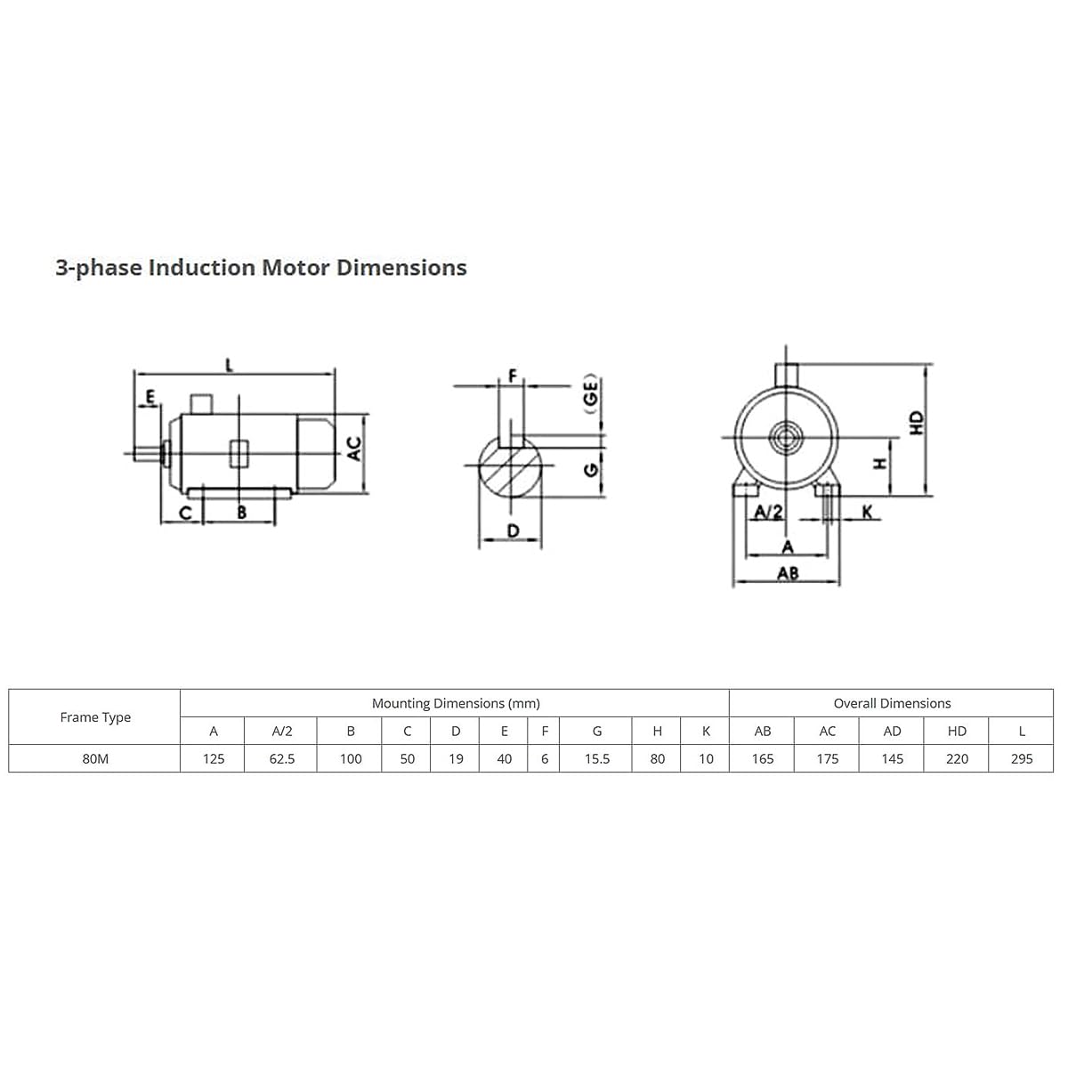
Figure 3: Motor Dimensions Diagram
This diagram illustrates the key mounting and overall dimensions of the motor, with labels for each measurement point.
| Frame Type | Mounting Dimensions (mm) | Overall Dimensions (mm) | |||||||||||||
|---|---|---|---|---|---|---|---|---|---|---|---|---|---|---|---|
| A | A/2 | B | C | D | E | F | G | H | K | AB | AC | AD | HD | L | |
| 80M | 125 | 62.5 | 100 | 50 | 19 | 40 | 6 | 15.5 | 80 | 10 | 165 | 175 | 145 | 220 | 295 |
5. Setup and Installation
5.1 Safety Precautions
- Ensure power is disconnected before any installation or maintenance.
- Installation should be performed by qualified personnel only.
- Wear appropriate personal protective equipment (PPE).
- Verify that the supply voltage and frequency match the motor's specifications.
- Ensure proper grounding of the motor.
5.2 Mounting
The motor is designed for horizontal foot mounting (B3). Use the pre-drilled holes on the fixed base for secure installation. Ensure the mounting surface is stable, level, and capable of supporting the motor's weight (15kg) and operational forces.
Refer to the dimensions in Section 4.1 for precise mounting hole spacing.
5.3 Electrical Connections
The motor requires a 3-phase power supply. The default connection for nominal output ≤4hp (3kW) is a Star (Y) connection for 380V. For 220V operation, you may need to change to a Delta (Δ) connection. Consult a qualified electrician for wiring.
Wiring must comply with local electrical codes and regulations.

Figure 4: Wiring Diagrams
This image provides standard wiring diagrams for three-phase squirrel-cage induction motors, including Star (Y), Delta (Δ), and Star-Delta (Y-Δ) connections, as well as configurations for two-speed motors.
- Star (Y) Connection: Typically used for higher voltage (e.g., 380V). Connect terminals W2, U2, V2 together, and connect L1, L2, L3 to U1, V1, W1 respectively.
- Delta (Δ) Connection: Typically used for lower voltage (e.g., 220V). Connect U1-W2, V1-U2, W1-V2, then connect L1, L2, L3 to these respective junctions.
- Grounding: Always connect the motor's ground terminal to a reliable earth ground.
6. Operating Instructions
6.1 Pre-Operation Checks
- Confirm all electrical connections are secure and correct.
- Ensure the motor is properly mounted and aligned with the driven equipment.
- Check for any obstructions around the motor's cooling fan and ventilation holes.
- Verify that the ambient temperature is within the specified range (-15°C to +40°C).
6.2 Starting the Motor
- Apply power to the motor circuit.
- Observe the motor for any unusual noises, vibrations, or overheating during the initial startup.
- If any abnormalities are detected, immediately shut off power and investigate the cause.
6.3 Stopping the Motor
To stop the motor, simply disconnect the power supply to the motor circuit.
7. Maintenance
Regular maintenance is crucial for ensuring the longevity and optimal performance of your ATO AC Induction Motor. Always disconnect power before performing any maintenance.
7.1 Routine Checks (Monthly)
- Visual Inspection: Check for any signs of physical damage, corrosion, or loose connections.
- Cleanliness: Ensure the motor's cooling fins and ventilation openings are free from dust, dirt, and debris to maintain efficient heat dissipation.
- Noise and Vibration: Listen for any unusual noises or feel for excessive vibrations during operation.
- Temperature: Monitor the motor's operating temperature. Excessive heat can indicate a problem.
7.2 Bearing Lubrication
This motor typically uses sealed bearings that are lubricated for life and do not require routine re-lubrication. If the motor exhibits unusual bearing noise, consult a qualified technician for inspection and potential bearing replacement.
7.3 Electrical Connections
Periodically check all electrical connections in the junction box for tightness and signs of wear or corrosion. Tighten any loose connections.
8. Troubleshooting
This section provides guidance for common issues. For problems not listed or if solutions do not resolve the issue, contact technical support.
| Problem | Possible Cause | Solution |
|---|---|---|
| Motor does not start | No power supply Incorrect wiring Overload protection tripped Motor seized | Check power source and circuit breaker Verify wiring against diagrams (Figure 4) Reset overload protection; check for mechanical issues Inspect for mechanical obstruction or bearing failure |
| Motor overheats | Insufficient ventilation Overload Incorrect voltage/frequency Bearing failure | Clear obstructions from cooling fins/fan Reduce load on motor Verify power supply matches specifications Inspect bearings; replace if necessary |
| Excessive noise or vibration | Loose mounting Misalignment with driven equipment Worn bearings Unbalanced rotor | Tighten mounting bolts Check and correct alignment Inspect and replace bearings Consult a specialist for rotor balancing |
| Motor runs slowly or with reduced power | Low voltage Overload Partial winding fault | Check supply voltage Reduce load Consult a qualified electrician for motor testing |
9. Warranty and Support
For warranty information, please refer to the documentation provided at the time of purchase or contact your retailer. ATO offers technical support for its products.
For further assistance, please visit the ATO Store on Amazon or contact customer service.


