1. Product Overview
This manual provides essential information for the installation, operation, and maintenance of the STEPPERONLINE A6 Series AC Servo Motor and Driver Kit. This kit includes a 220VAC 750W servo motor and a single-phase 220V 750W servo driver, supporting Pulse, RS485, and Analog communication. The motor features a built-in 17-bit multi-turn absolute encoder, ensuring precise control performance.
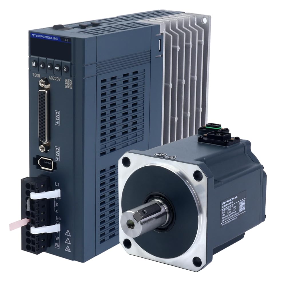
Figure 1: STEPPERONLINE A6 Series 750W AC Servo Motor Driver. This image displays the servo driver unit, highlighting its compact design and various connection ports.
Kit Contents:
- 1 x A6-750RS: 750W Pulse/RS485/Analog AC Servo Motor Driver
- 1 x A6M80-750H2A1-M17: 750W AC Servo Motor (3000rpm, 2.39Nm, 17-Bit Encoder, IP67)
- 1 x AS7-C-PWR075-3.0: 3.0m Motor Cable
- 1 x AS7-C-ENC075-3.0: 3.0m Encoder Cable
2. Safety Information
Read all instructions carefully before installation and operation. Failure to follow safety precautions may result in personal injury or equipment damage. Always disconnect power before performing any wiring or maintenance. Ensure proper grounding of all components. This equipment should only be installed and operated by qualified personnel.
3. Components Identification
3.1 Servo Driver (A6-750RS)

Figure 2: STEPPERONLINE A6-750RS Servo Driver. This image shows the front and side views of the servo driver, detailing its cooling fins and connection interfaces.
The servo driver is the control unit for the motor, converting control signals into motor movements. It features various input/output ports for power, motor connection, encoder feedback, and communication interfaces.
3.2 Servo Motor (A6M80-750H2A1-M17)

Figure 3: STEPPERONLINE A6M80-750H2A1-M17 Servo Motor. This image displays the servo motor with its shaft and mounting flange, along with the connector for the encoder and power.
The servo motor is a high-performance AC motor designed for precise position, velocity, and torque control. It is equipped with a 17-bit multi-turn absolute encoder for accurate feedback and an IP67 rating for environmental protection.
3.3 Cables

Figure 4: STEPPERONLINE Motor and Encoder Cables. This image shows the 3.0m motor cable and 3.0m encoder cable, essential for connecting the servo motor to the driver.
The kit includes dedicated motor and encoder cables for reliable connection between the servo motor and driver. The encoder cable is crucial for utilizing the multi-turn absolute encoder functionality, especially when used with a battery box.
4. Installation and Wiring
4.1 Mounting
Mount the servo driver in a well-ventilated enclosure to ensure adequate heat dissipation. Secure the servo motor to a stable surface using appropriate fasteners, ensuring proper alignment with the load. Avoid mounting in areas subject to excessive vibration, dust, or moisture.
4.2 Wiring Connections
All wiring should be performed with the power supply disconnected. Refer to the wiring diagram below for correct connections. Ensure all connections are secure to prevent intermittent operation or damage.

Figure 5: STEPPERONLINE A6 Series Wiring Diagram. This diagram illustrates the power input connections for the 100W/400W/750W servo drivers, showing L1, L2, P, C, N, U, V, W, and PE terminals.
Power Wiring: Connect the single-phase 220VAC power supply to the L1 and L2 terminals of the servo driver. Ensure the protective earth (PE) terminal is properly grounded.
Motor Wiring: Connect the motor power cable to the U, V, W terminals on the driver and the corresponding terminals on the motor. The motor cable also includes connections for the motor brake, if applicable.
Encoder Wiring: Connect the encoder cable from the motor's encoder port to the CN2 port on the servo driver. This connection is vital for feedback and absolute positioning. For multi-turn absolute encoder functionality, ensure the 3m encoder cable with a battery box is used.
Control Signal Wiring: Connect pulse, direction, and enable signals to the CN1 port as per your control system requirements. The driver supports Pulse, RS485, and Analog communication interfaces.
5. Operating Modes
The A6 series servo driver supports various control modes to suit different application needs. These include:
- Position Control Mode
- Velocity Control Mode
- Torque Control Mode
- Position-Velocity Mode
- Position-Torque Mode
- Torque-Velocity Mode
- Position-Velocity-Torque Mode (Dual Mode Switching)
Configuration of these modes and their parameters is typically done via software provided by STEPPERONLINE or through the driver's built-in interface. Refer to the detailed programming manual for specific parameter settings and communication protocols (Pulse, RS485, Analog).
6. Specifications
6.1 Servo Driver Specification (A6-750RS)
| Parameter | Value |
|---|---|
| Part Number | A6-750RS |
| Communication | Pulse/RS485/Analog |
| Speed Loop Bandwidth | 2KHz |
| Encoder Type | 17-bit absolute encoder |
| Rated Voltage | Single-phase 220VAC |
| Rated Power | 750W |
| Dimension | 170 x 174 x 50mm |
6.2 Servo Motor Specification (A6M80-750H2A1-M17)
| Parameter | Value |
|---|---|
| Part Number | A6M80-750H2A1-M17 |
| Rated Voltage | 220VAC |
| Rated Power | 750W |
| Rated Torque | 2.39Nm |
| Peak Torque | 8.36Nm |
| Rated Speed | 3000rpm |
| Peak Speed | 6000rpm |
| Rated Current | 4.60A |
| Peak Current | 16.30A |
| Torque Constant | 0.52N.m/A |
| Back EMF Constant | 34.40V/krpm |
| Resistance | 0.47 ohms |
| Inductance | 2.80mH |
| Inertia | 1.72kg*m²*10⁻⁴ |
| Poles | 10 |
| Encoder | 17-bit multi-turn absolute, magnetic encoder |
| IP Rating | IP67 |
| Shaft Diameter | 19mm |
| Cable Length | 3m |
7. Maintenance
Regular maintenance ensures optimal performance and longevity of your servo system. Perform the following checks periodically:
- Visual Inspection: Check for any loose connections, damaged cables, or signs of overheating on the driver and motor.
- Cleaning: Keep the driver's cooling fins free from dust and debris to ensure efficient heat dissipation. Use compressed air if necessary.
- Environmental Conditions: Ensure the operating environment remains within specified temperature and humidity ranges.
- Firmware Updates: Check the manufacturer's website for any available firmware updates for the servo driver.
8. Troubleshooting
If you encounter issues with your servo system, refer to the following common troubleshooting steps:
- No Power: Verify that the power supply is connected correctly and providing the rated voltage. Check fuses or circuit breakers.
- Motor Not Moving: Ensure the enable signal is active. Check control signal connections (Pulse, Direction, Analog). Verify motor and encoder cable connections.
- Motor Overheating: Check for excessive load on the motor. Ensure proper ventilation for the driver and motor. Verify motor parameters are correctly set.
- Encoder Errors: Inspect the encoder cable for damage. Ensure the encoder is securely connected. If using multi-turn absolute functionality, check the battery box connection.
- Abnormal Noise/Vibration: Check for mechanical issues with the load or motor mounting. Verify motor tuning parameters.
For persistent issues, consult the detailed programming manual or contact technical support.
9. Warranty and Support
STEPPERONLINE products are designed for reliability and performance. For warranty information, please refer to the terms and conditions provided at the time of purchase or visit the official STEPPERONLINE website.
Technical Support:
For technical assistance, troubleshooting guidance, or inquiries regarding your STEPPERONLINE A6 Series AC Servo Motor Kit, please contact STEPPERONLINE customer support through their official website or authorized distributors. When contacting support, please have your product model number (A6-RS750H2A1-M17) and a detailed description of the issue ready.