
1. Introduction to Circuit Paper
The Mctrlvp P2.5-1921-2121(VL) Circuit Paper is a specialized double-layer flexible circuit board designed for the repair of LED display screens. Its ultra-thin profile, measuring only 0.08-0.1mm in thickness, makes it ideal for precise repairs.
LED display screens can experience PCB pad detachment due to impacts during installation, disassembly, or transportation. This Circuit Paper provides an effective solution for repairing these damaged PCB pads, restoring the functionality of the LED module.
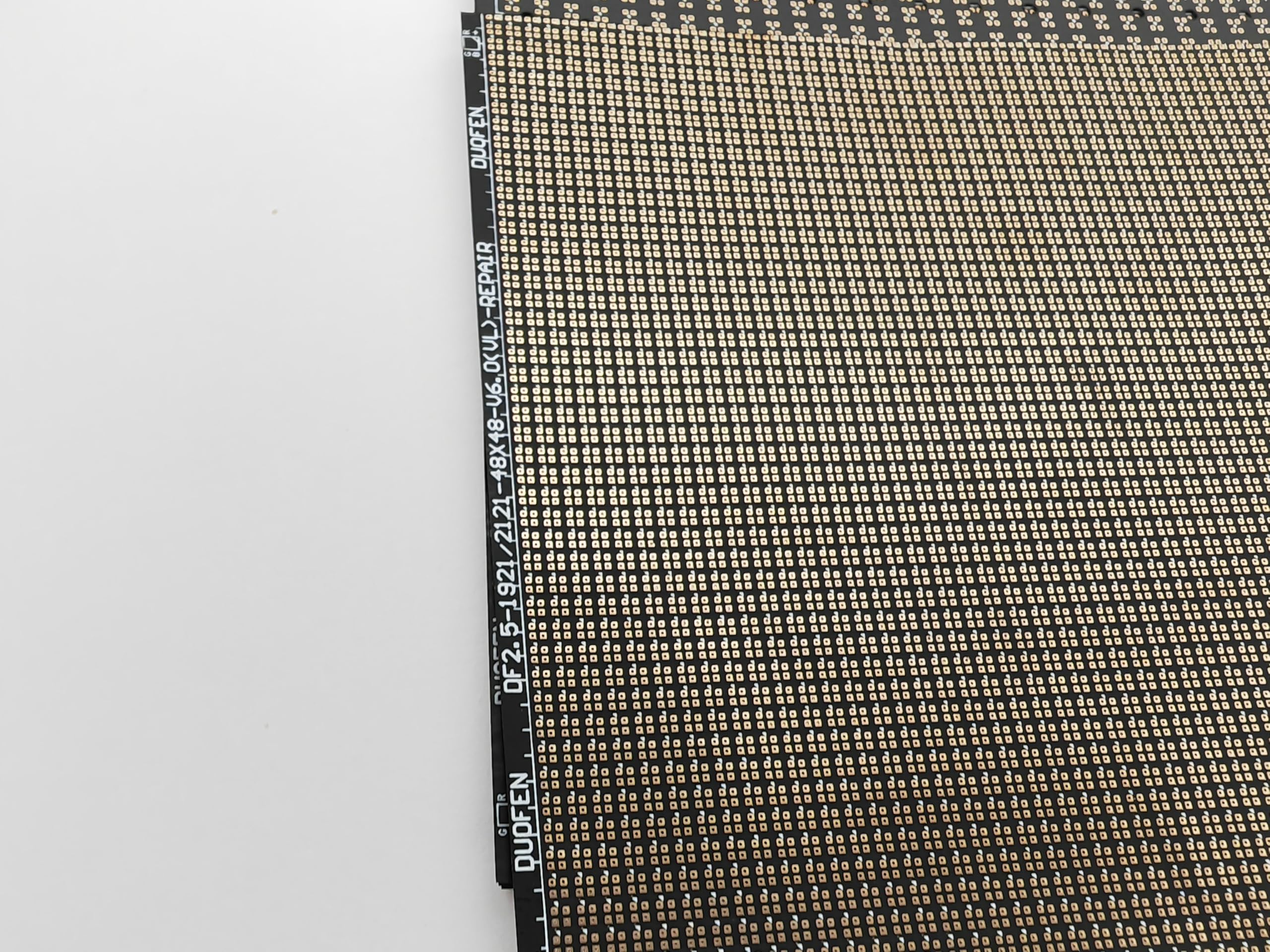
Image 1.1: Overview of the Mctrlvp P2.5-1921-2121(VL) Circuit Paper.
2. Setup: Choosing the Correct Circuit Paper
Selecting the appropriate Circuit Paper is crucial for successful repair. Follow these guidelines:
- Pixel Pitch Consistency: The pixel pitch of the original LED module must match that of the Circuit Paper.
- LED Bead Specifications: Ensure the specifications of the original LED beads are consistent with the Circuit Paper.
- Lamp Orientation: Some products feature differences between vertical and horizontal lamps. If the original LED module uses vertical lamps, select a Circuit Paper designed for vertical lamps.
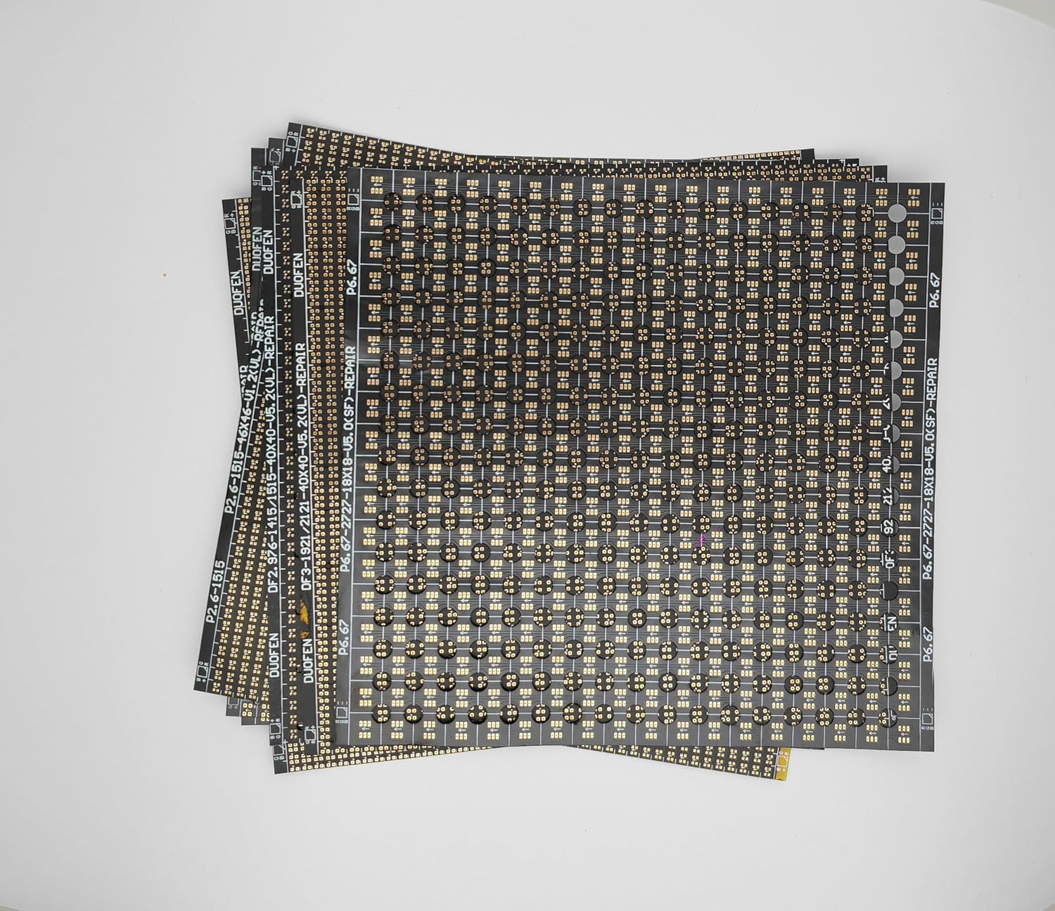
Image 2.1: A selection of Mctrlvp Circuit Papers, illustrating variations for different LED display types.
3. Operating Instructions: Repairing PCB Pads
To repair a damaged PCB pad using the Circuit Paper, gather the necessary tools and follow these steps carefully:
Required Tools and Consumables:
- Anti-static bracelet
- Soldering iron
- Hot air gun
- Multimeter
- Tweezers
- Tin wire
- Solder paste
- Scissors
- Screwdriver
- Replacement lamp beads
- Circuit Paper
- IC (if required for specific repairs)
Repair Procedure:
- Step 1: Prepare the Damaged Pad. Carefully scrape the damaged PCB pad with a knife blade to remove any debris or loose material. Clean the area thoroughly with alcohol to prevent short circuits when applying the Circuit Paper.
- Step 2: Prepare the Circuit Paper. Cut the Circuit Paper to the appropriate size for the repair area. Apply a thin layer of tin to both sides of the pad on the Circuit Paper. Avoid excessive tin to prevent short circuits between lamp feet.
- Step 3: Attach the Circuit Paper. Set your soldering iron temperature to approximately 320 ℃. Using tweezers, carefully position the tin-coated Circuit Paper over the damaged PCB pad, aligning it precisely with the soldering pad of the PCB lamp tube. Gently press it into place.
- Step 4: Fuse the Circuit Paper. Heat the Circuit Paper with the soldering iron or a hot air gun until it fully fuses with the PCB pad. Ensure that common poles are correctly aligned during this process.
- Step 5: Install and Test Lamp Beads. Light up the module and display a full white screen. Adjust the brightness to a comfortable level for the naked eye by sweeping obliquely. Weld the replacement lamp beads onto the Circuit Paper, paying close attention to the polarity direction of the beads. Before welding, use a multimeter to test the pins for proper connection.
- Step 6: Post-Repair Sealing (Indoor Modules). After the module test is successfully completed, fill the repaired area with glue if it is an indoor module. Outdoor modules typically do not require this step.

Image 3.1: Detailed view of the Circuit Paper pads, ready for tinning and application.
4. Maintenance
For indoor LED modules, it is recommended to fill the repaired area with appropriate glue after successful testing. This step helps to protect the newly repaired connections and ensures long-term stability of the LED display.
5. Troubleshooting
If the LED module does not function correctly after repair, review the following:
- Alignment: Verify that the Circuit Paper and lamp beads are correctly aligned with the PCB pads and that common poles are matched.
- Connections: Use a multimeter to check for proper electrical continuity and to identify any short circuits or open connections.
- Polarity: Ensure that the lamp beads are welded with the correct polarity.
- Tools: Confirm that all tools, especially the soldering iron, are at the correct temperature and functioning properly.
6. Specifications
- Model: P2.5-1921-2121(VL) Circuit Paper
- Material: Double-layer flexible circuit board
- Thickness: 0.08 - 0.1 mm
- Compatible LED Bead Types: 1921-2121 (for P2.5 model)
- Common Sizes: 120x125mm, 80x85mm (varies by pixel pitch)
- Compatible Pixel Pitches (Examples): P1.25, P1.538, P1.5625, P1.667, P1.839, P1.86, P1.875, P1.923, P2, P2.5, P2.976, P3, P3.91, P4, P4.81, P5
7. Warranty and Support
Warranty information for the Mctrlvp P2.5-1921-2121(VL) Circuit Paper is not provided in this manual. For specific warranty details or technical support, please contact your retailer or the manufacturer directly.