Introduction
The Briidea RV Automatic Transfer Switch is designed to seamlessly manage power sources for your RV, speedboat, or other high-power equipment requiring emergency power supply. This 30 Amp, 120/240 VAC unit prioritizes generator power, automatically switching to utility power when the generator is off and initiating generator power upon utility outage. Its advanced design ensures convenience and reliability.

Image: The Briidea Automatic Transfer Switch integrated into an RV power system, ensuring continuous power supply.
Important Safety Information
Please read and understand all safety instructions before installation or operation. Failure to follow these instructions may result in electric shock, fire, or serious injury.
- Professional Installation Recommended: All power sources must be turned off before installation or servicing. Refer service to a qualified electrician. This device handles high voltage and current.
- Overcurrent Protection: Ensure proper overcurrent protection is in place for your electrical system.
- Dual Protection: The switch features mechanical interlocks and precise control circuits to prevent both power sources (shore and generator) from simultaneously entering the AC distribution board, which could cause a short circuit.
- Environmental Protection: The durable enclosure is waterproof, rust-proof, and anti-corrosion with an IP65 rating, designed for longevity.

Image: Key features of the Briidea Automatic Transfer Switch, highlighting safety, durability, wide application, and ease of installation.
Product Specifications
| Specification | Value |
|---|---|
| Product Dimensions | 3 x 4 x 2 inches |
| Item Weight | 3.14 Pounds |
| Item Model Number | LD-141 |
| Manufacturer | briidea |
| Operation Mode | Automatic |
| Current Rating | 30 Amps |
| Operating Voltage | 120/240 Volts AC |
| Contact Type | Normally Open |
| Connector Type | Clamp |
| Terminal | Blade |
| Circuit Type | 3-way |
| Actuator Type | Push Button |
Package Contents
Verify that all items are present before beginning installation:
- 1 x Briidea RV Automatic Transfer Switch
- Mounting Hardware (screws, anchors)

Image: The automatic transfer switch along with its mounting accessories.
Setup and Installation
The Briidea Automatic Transfer Switch is designed for straightforward installation, but due to the high voltage involved, it is strongly recommended that installation be performed by a qualified electrician. An easy-to-remove protective cover with a wiring diagram is provided inside the unit.
1. Pre-Installation Checklist
- Ensure all power sources (shore power, generator) are disconnected and locked out before beginning any work.
- Confirm the installation location is dry, protected, and allows for proper ventilation and access for wiring.
- Gather necessary tools, including wire strippers, screwdrivers, and a multimeter.
- Important Note for DIYers: The enclosure features dimpled areas for knockouts, but these are not pre-cut. You will need appropriate tools (e.g., panel knockout set or hole saws) to create the necessary openings for wiring.
2. Mounting the Transfer Switch
Mount the transfer switch securely to a stable surface using the provided mounting hardware. Consider the dimensions of the unit (approximately 10.5 inches high, 6.3 inches wide, and 2.5 inches deep) when selecting your mounting location.
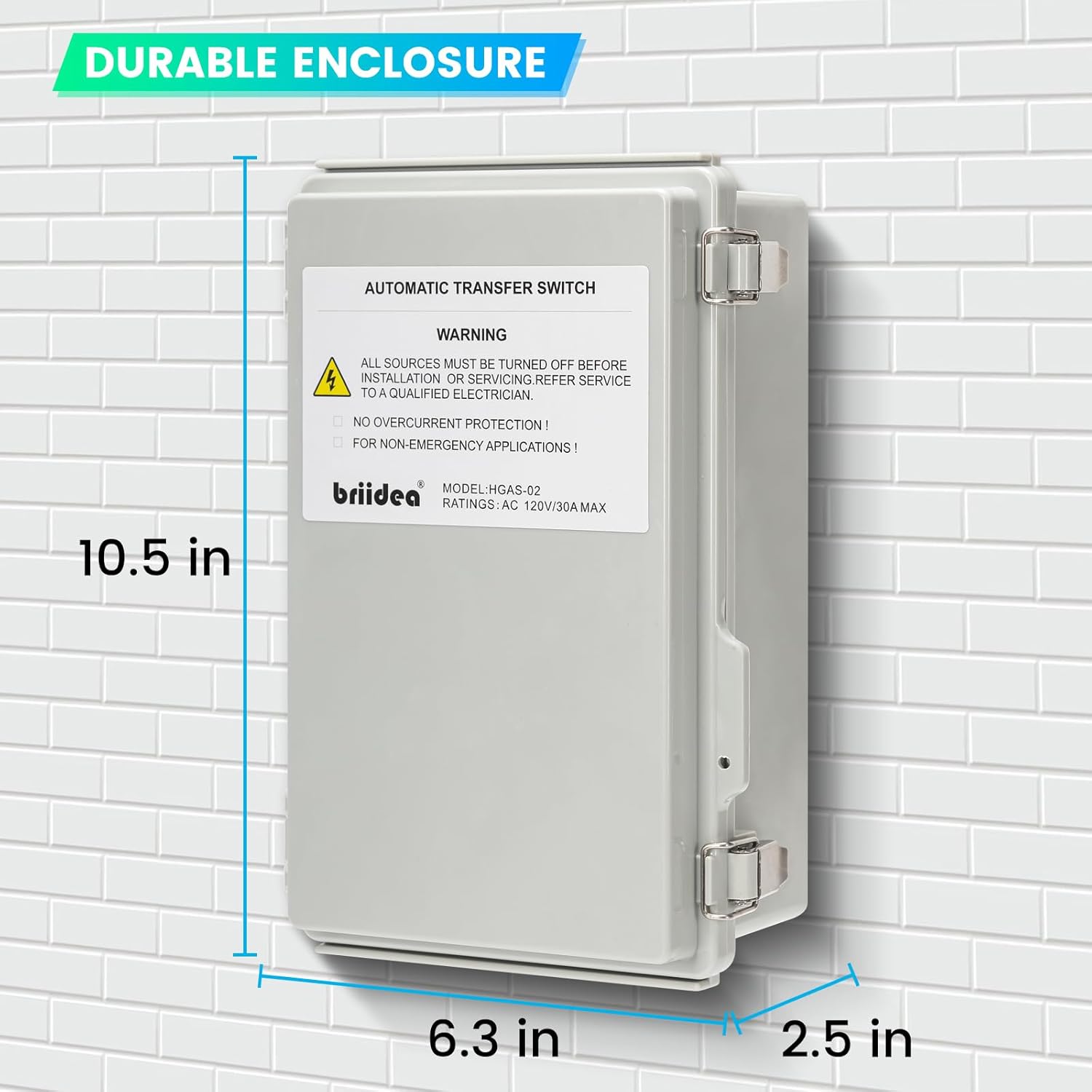
Image: Physical dimensions of the Briidea Automatic Transfer Switch for mounting reference.
3. Wiring Diagram and Connections
Refer to the detailed wiring diagram provided inside the unit's protective cover and the diagrams below for correct connections. The internal copper wiring is designed for conciseness and durability.
- Connect the Shore Power Line and Neutral to the designated "SHORE" terminals.
- Connect the Generator Power Line and Neutral to the designated "GEN" terminals.
- Connect the Load Line and Neutral (leading to your RV's main panel) to the designated "LOAD" terminals.
- Ensure all ground wires are connected to the ground bar.
- Wiring Tip: The lightweight control circuit wires attach to the same screws as the heavy power wires. When loosening screws for heavy wires, ensure the lightweight wires do not come loose. Visually verify that all wires are properly compressed onto their contacts as you tighten the screws.

Image: Internal view of the transfer switch, showing the wiring terminals and an overview of the wiring diagram.
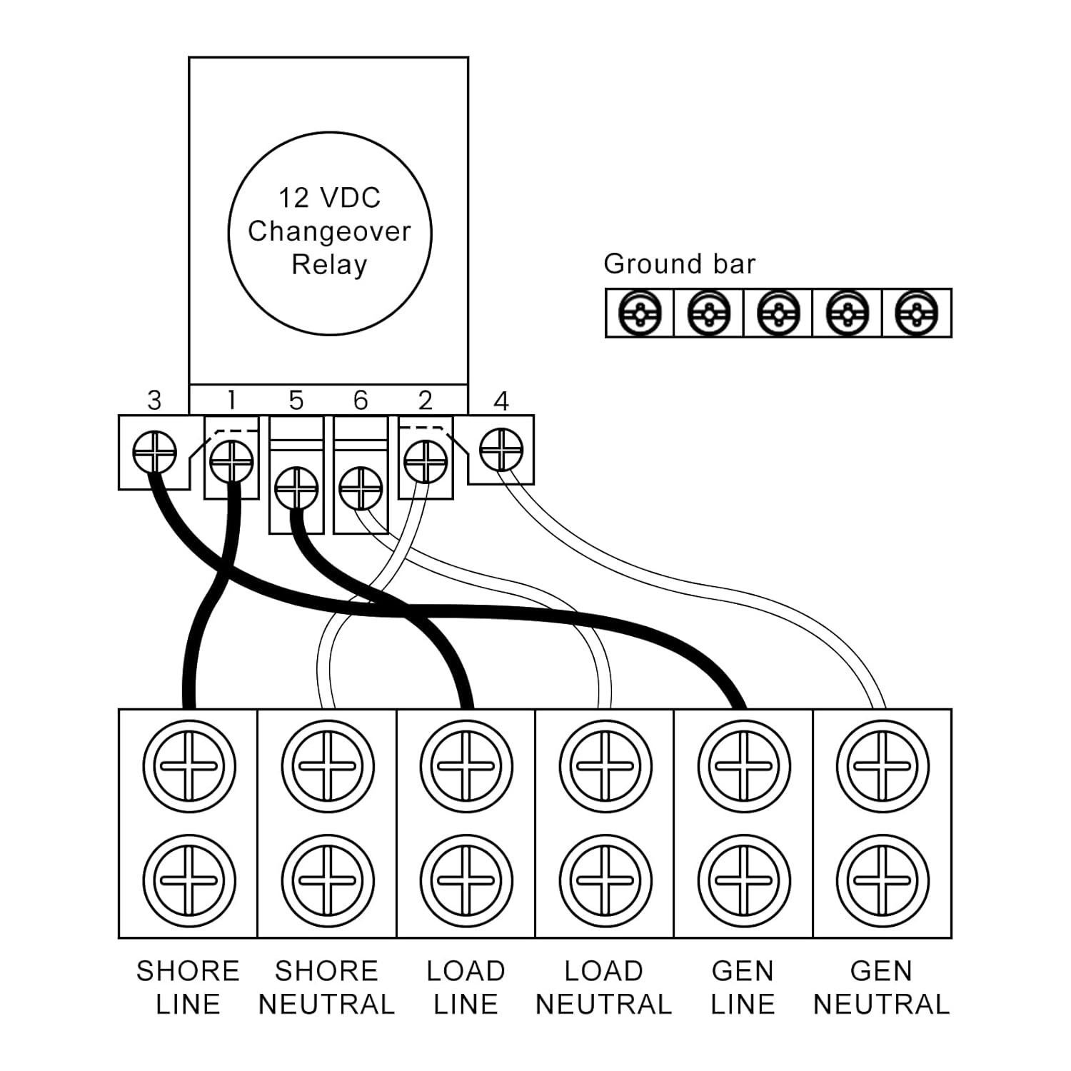
Image: A detailed schematic of the wiring connections for the transfer switch, including Shore, Load, and Generator inputs/outputs, and the ground bar.

Image: Illustrative diagram demonstrating how the transfer switch connects between a portable generator, power inlet box, and the main electrical panel.
4. Initial Power-Up
Once all wiring is complete and verified, carefully restore power. The unit will automatically detect the active power source.
Operating Instructions
Automatic Power Transfer
The Briidea Automatic Transfer Switch operates with a priority for generator power. Its intelligent design ensures a smooth transition between power sources:
- Generator Priority: When generator power is applied, the switch will prioritize it. If the generator stops running, the switch automatically transfers to utility (shore) power.
- Generator Restart: Upon generator restart, a green indicator light will illuminate, confirming that generator power is active and being utilized.
- Utility Outage Response: The switch continuously monitors utility power. In the event of a utility power outage, the generator will automatically start (if configured for auto-start) and the switch will transfer the load to generator power.
Delay Circuit Function
When transferring to generator power, the built-in MCU precise control circuit incorporates a 20-second delay. This delay ensures that the generator voltage stabilizes before being transmitted to your electrical system, providing protection for your appliances. This delay function can be turned off if not required for your specific setup.

Image: The internal components of the transfer switch, emphasizing the mechanical interlocks and control circuits that provide double protection against short circuits.
Maintenance
Enclosure Care
The Briidea Automatic Transfer Switch features a durable enclosure with a coating process that provides waterproof, rust-proof, and anti-corrosion properties, rated at IP65. To ensure the longevity of your unit:
- Periodically inspect the enclosure for any signs of damage or wear.
- Keep the exterior clean from dirt and debris. Use a soft, damp cloth for cleaning. Do not use harsh chemicals or abrasive cleaners.
- Ensure the enclosure seals are intact to maintain its waterproof rating.
Troubleshooting
Common Issues and Solutions
- No Power Transfer:
- Verify that both shore power and generator power sources are active and providing correct voltage.
- Check all wiring connections for tightness and proper seating, especially where lightweight control wires meet heavy power wires. Loose connections can prevent proper operation.
- Ensure circuit breakers for both input sources and the load are not tripped.
- Unit Trips Breaker Immediately:
- This indicates a direct short circuit. Immediately disconnect all power.
- Re-verify all wiring connections against the diagram. Pay close attention to Line and Neutral connections to ensure no cross-wiring.
- If the issue persists after verifying wiring, contact a qualified electrician or Briidea customer support, as the unit may be defective.
- Generator Starts but No Transfer:
- Check if the 20-second delay circuit is active. Wait for the delay to complete.
- Ensure the generator is producing stable voltage and frequency.
Warranty and Support
For technical assistance, troubleshooting beyond this manual, or warranty inquiries, please contact Briidea customer support. Refer to your purchase documentation for specific warranty terms and contact information.
You can visit the official Briidea store for more information and support: Briidea Store on Amazon