1. Introduction
This manual provides essential information for the safe and effective use of your CRIDENG 1200W 20A DC Boost Converter Power Module. This non-isolated boost module is designed to convert a lower DC input voltage to a higher DC output voltage, suitable for various applications requiring a stable and adjustable power supply. Please read these instructions carefully before installation and operation.
2. Product Features
- Durable Construction: Made from robust materials to ensure strength and longevity.
- Adjustable Output: Each module allows individual current adjustment up to 15A, enabling customized power distribution.
- Wide Temperature Range: Operates effectively within a temperature range of -40 to +85 degrees Celsius. Adequate heat dissipation is required at higher ambient temperatures.
- High Conversion Efficiency: Achieves up to 95% conversion efficiency, which may vary based on input/output voltage, current, and differential pressure.
- Comprehensive Protection: Features over-current protection with adjustable output current limit and double short-circuit protection (input 20A fuse) for safe and reliable operation.
3. Specifications
| Attribute | Value |
|---|---|
| Module Type | Non-isolated Boost Module (BOOST) |
| Input Voltage | 10 - 60V DC (via jump cap switch) |
| Input Current | 20A |
| Quiescent Current | 15mA (at 12V to 20V, increases with higher output voltage) |
| Output Voltage | 12 - 80V DC (continuously adjustable) |
| Output Current | 20A MAX (strengthen heat dissipation if greater than 18A) |
| Constant Current Range | 20A |
| Output Power | Input voltage × 20A (e.g., 12V × 20A = 240W, 60V × 20A = 1200W) |
| Installation | Four 3mm screws |
| Connection Type | Press-fit terminal output |
| Dimensions (L x W x H) | 85mm x 63mm x 64mm |
| Working Temperature | -40 to +85 degrees Celsius |
| Working Frequency | 150KHz |
| Conversion Efficiency | Up to 95% |
| Over-current Protection | Yes (with current reduction adjustment, output current automatically reduces to 5A if limit exceeded) |
| Short-circuit Protection | Yes (input 20A fuse, double protection) |
| Input Reverse Polarity Protection | No (connect a diode in series if required) |
| Output Counter Fill Protection | Yes (no blocking diode needed for charging) |
4. Setup and Installation
Proper installation is crucial for the safe and efficient operation of the boost converter module.
4.1. Physical Installation
- Mounting: Secure the module using four 3mm screws through the designated mounting holes. Ensure it is mounted on a stable, non-conductive surface.
- Heat Dissipation: Ensure adequate ventilation around the module, especially if operating at higher currents or ambient temperatures. Strengthening heat dissipation may be necessary.
4.2. Electrical Connection
- Input Voltage: The default input voltage range is 10-60V DC. Connect your DC power source to the input terminals (VIN+ and VIN-).
- Output Connection: Connect your load device to the output terminals (VOUT+ and VOUT-) using the press-fit terminals.
- Reverse Polarity: The module does not have input reverse polarity protection. If this is a concern for your application, connect a diode in series with the input.
5. Operating Instructions
Follow these steps to adjust the output voltage and current of the boost converter module.
5.1. Output Voltage Adjustment
- Connect the input power source to the module.
- Adjust the V-adj potentiometer (voltage adjustment) to set the desired output voltage. Use a multimeter to monitor the output voltage and match it to the requirements of your load equipment.
5.2. Output Current Adjustment
- Before connecting the load, rotate the I-adj potentiometer (current adjustment) counterclockwise for approximately 30 turns to minimize the output current.
- Connect your load device to the output terminals.
- Slowly adjust the I-adj potentiometer clockwise until the required current for your load is reached. Monitor the current with an ammeter.
5.3. Battery Charging (Constant Current Mode)
When using the module for battery charging:
- Ensure the battery is discharged before connecting it to the module's output.
- Adjust the CC potentiometer (constant current) to the desired charging current.
- Note that the charging current will decrease as the battery approaches full charge.
Important Safety Note: Do not attempt to adjust the current by short-circuiting the output. The boost module's circuit structure is not designed for this and may result in damage.
6. Maintenance
To ensure the longevity and optimal performance of your CRIDENG DC Boost Converter Power Module, consider the following maintenance guidelines:
- Cleaning: Periodically inspect the module for dust and debris. Use a soft, dry brush or compressed air to gently clean the components, especially the heat sink, to maintain efficient cooling.
- Ventilation: Ensure that the module's operating environment provides adequate airflow to prevent overheating. Do not obstruct the heat sink.
- Connections: Regularly check all electrical connections to ensure they are secure and free from corrosion. Loose connections can lead to poor performance or damage.
- Environmental Conditions: Operate the module within its specified temperature and humidity ranges. Avoid exposure to moisture or corrosive substances.
7. Troubleshooting
If you encounter issues with your CRIDENG DC Boost Converter Power Module, refer to the following common troubleshooting steps:
- No Output Voltage:
- Verify that the input voltage is within the specified range (10-60V DC).
- Check all input and output connections for proper contact and polarity.
- Ensure the V-adj potentiometer has not been adjusted to its minimum setting.
- Output Current Too Low/High:
- Adjust the I-adj potentiometer as described in the Operating Instructions.
- Confirm that the load's current demand is within the module's 20A maximum output.
- Check for any short circuits in the load or output wiring, which could trigger over-current protection.
- Overheating:
- Ensure adequate ventilation and airflow around the module.
- Reduce the load if it is consistently drawing near the maximum current.
- Verify that the ambient temperature is within the operating range.
- Module Not Functioning:
- Check the input 20A fuse for continuity. Replace if blown.
- Inspect the module for any visible damage or burnt components.
If problems persist after following these steps, contact customer support for further assistance.
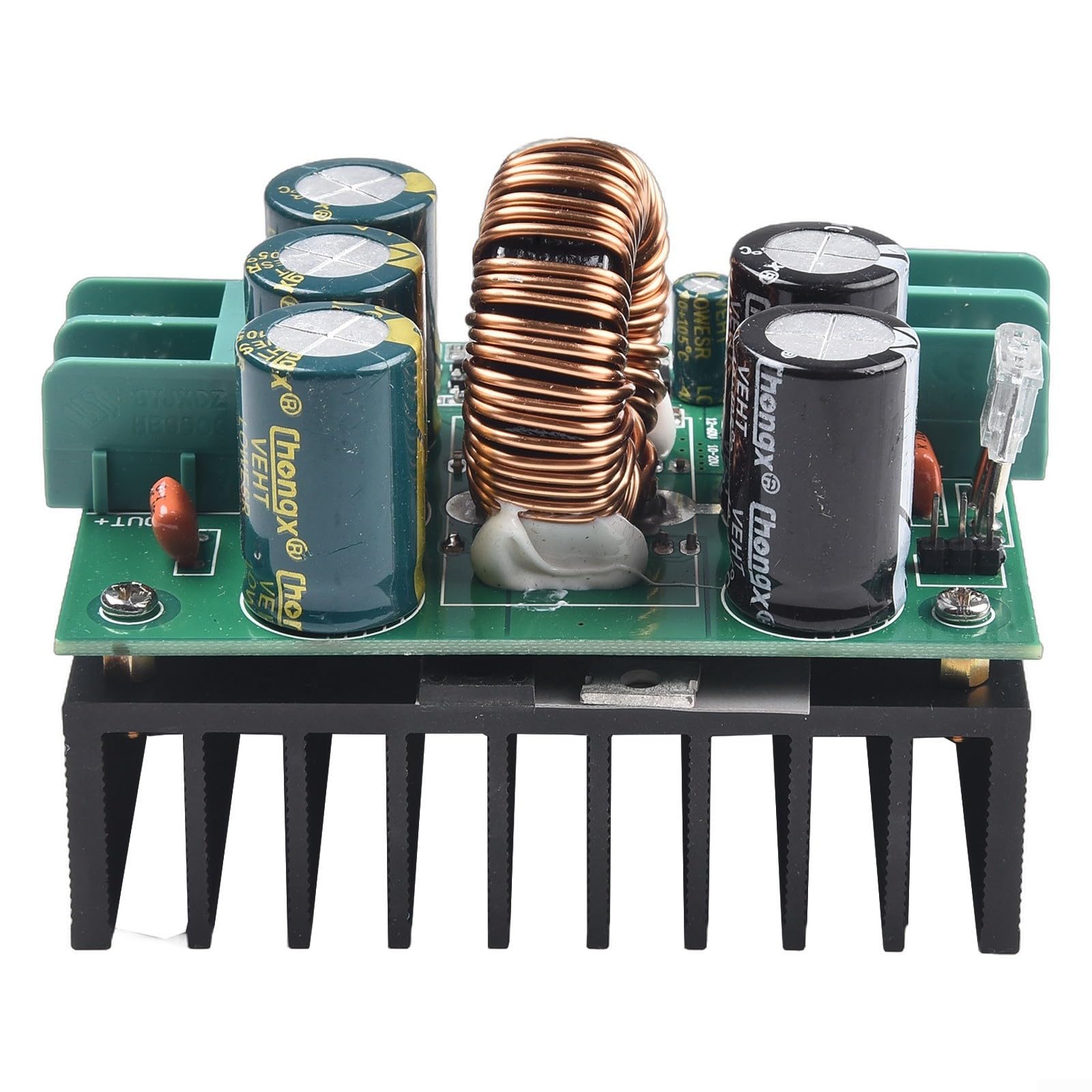
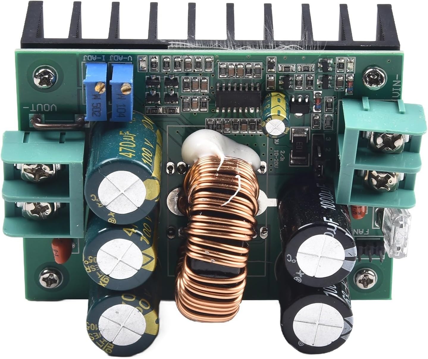
8. Product Images


9. Official Product Videos
There are no official product videos available for this item at this time.
10. Warranty Information
Specific warranty details for the CRIDENG 1200W 20A DC Boost Converter Power Module are not provided in this manual. Please refer to the product packaging or the retailer's website for applicable warranty terms and conditions.
11. Customer Support
For technical assistance, troubleshooting, or inquiries regarding your CRIDENG 1200W 20A DC Boost Converter Power Module, please contact the retailer or manufacturer's customer support channels. Refer to your purchase documentation for contact information.