
1. Overview
This manual provides instructions for the installation, operation, and maintenance of your XBERSTAR 12V Bike Tail Light Turn Signals Kit. This kit is designed to enhance safety by providing clear turn indications for various vehicles, including motorcycles, electric bicycles, scooters, and standard bicycles.
2. Product Features
- Front and rear turn signal kit for motorcycles, e-bikes, scooters, and bicycles.
- Provides safety warnings during riding, enhancing visibility and peace of mind.
- IP65 waterproof rating ensures functionality in rainy or foggy conditions.
- High brightness LED tail lights are visible in various lighting conditions, including daytime.
- Sturdy and durable design with easy self-replacement capability.
3. Specifications
| Specification | Detail |
|---|---|
| Product Name | Small Oval Mini Turn Signal Kit |
| Product Number | EB-V0412 |
| LED Quantity per Light | 3SMD |
| Application | Turn signal / Indicator light |
| Color Temperature & Light Color | 3000K, Yellow |
| Operating Voltage | 12V |
| Luminous Flux | 200LM |
| Waterproof Rating | IP65 |
| Material | ABS+PC |
| Operating Temperature | -40℃ to +80℃ |
| Service Life | > 30,000 hours |
| Applicable Models | Motorcycles, Electric Bicycles, Scooters, Bicycles |
| Cable Length (Individual Lights) | Approximately 30cm |
| Total Cable Length (Kit) | Approximately 2.5M |
| Screw Outer Diameter | M10 |
4. What's in the Box
The XBERSTAR 12V Bike Tail Light Turn Signals Kit includes:
- 1 set of Front & Rear Turn Signals
- Wiring Harness with Connectors
- Handlebar Switch
- Mounting Brackets and Hardware
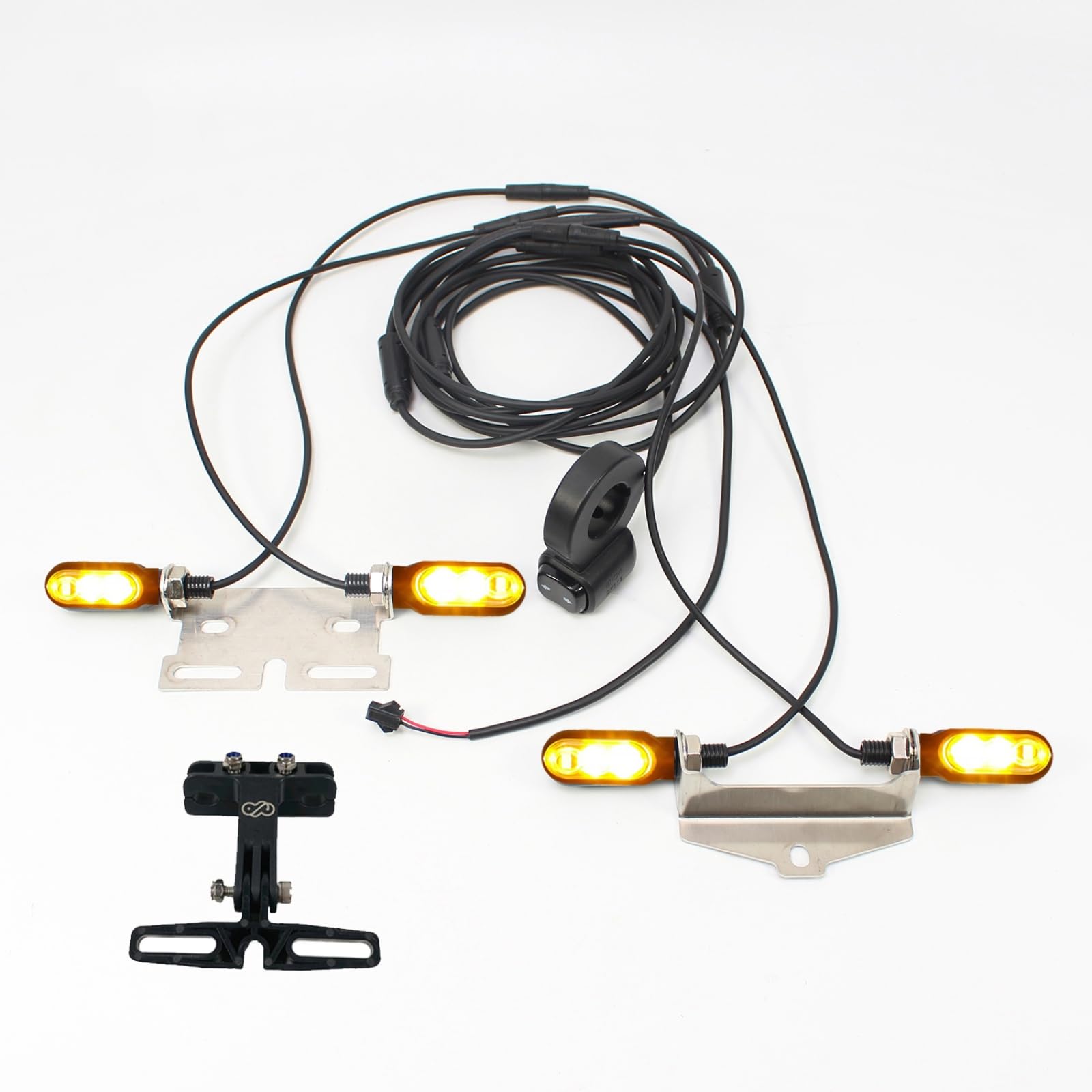
Image: All components of the XBERSTAR 12V Bike Tail Light Turn Signals Kit, including four signal lights, wiring harness, handlebar switch, and mounting brackets.
5. Setup & Installation
Before installation, ensure your vehicle has a 12V power source. Disconnect the power source before beginning installation to prevent electrical hazards.
5.1 Component Identification
- Signal Lights: Identify the four individual signal lights. Each light features 3SMD LEDs.
- Handlebar Switch: Locate the switch unit, designed for handlebar mounting, with left and right turn buttons.
- Wiring Harness: The main wiring harness connects all components. It includes keyed connectors to simplify wiring.
- Power Connector: The main power input connector, typically with red (positive) and black (negative) wires.

Image: A close-up view of one of the signal lights, showing the three LED elements and the threaded mounting base.

Image: The handlebar-mounted switch unit, featuring distinct buttons for left and right turn signals.

Image: The main power input connector, showing the red wire for positive and black wire for negative connection.
5.2 Wiring Diagram and Connections
Refer to the diagram below for proper wiring connections. The kit uses keyed connectors to prevent incorrect assembly.
- Power Input: Connect the main power input (1) to your vehicle's 12V power source. Ensure the red wire connects to positive (+) and the black wire to negative (-).
- Switch Connection: Connect the handlebar switch (2) to the main wiring harness.
- Front Turn Signals: Mount and connect the front left (3) and front right (4) turn signals to their respective connectors on the harness.
- Rear Turn Signals: Mount and connect the rear left (5) and rear right (6) turn signals to their respective connectors on the harness.

Image: An illustration demonstrating the recommended placement and wiring connections for the turn signal kit on an electric bicycle.
5.3 Mounting
Use the provided mounting brackets and hardware to securely attach the signal lights to your vehicle. Ensure the lights are positioned for maximum visibility from both front and rear. The handlebar switch should be mounted in an easily accessible location on your handlebars.
6. Operating Instructions
Once installed and connected to a 12V power source, operate the turn signals using the handlebar switch:
- Press the left arrow button on the switch to activate the left turn signals (front and rear). The lights will flash sequentially.
- Press the right arrow button on the switch to activate the right turn signals (front and rear). The lights will flash sequentially.
- To deactivate the turn signal, press the active arrow button again or the center button if available.
The sequential flashing of the 3SMD LEDs provides a clear and dynamic indication of your intended turn.
Video: A demonstration of the XBERSTAR 12V Turn Signals Light Electric Bicycle Tail Light kit, showing the functionality of the handlebar switch and the sequential flashing of the lights.
7. Maintenance
- Cleaning: Periodically clean the signal light lenses with a soft, damp cloth to ensure maximum light output and visibility. Avoid abrasive cleaners.
- Connection Check: Regularly inspect all wiring connections to ensure they are secure and free from corrosion or damage.
- Mounting Security: Verify that all signal lights and the handlebar switch are securely mounted and have not loosened due to vibrations during riding.
- Waterproof Integrity: While rated IP65, avoid prolonged submersion. Ensure all connectors are properly seated to maintain waterproof performance.
8. Troubleshooting
8.1 Lights Not Functioning
- Check Power Source: Ensure the 12V power source is active and providing power to the kit. Verify the red wire is connected to positive and black to negative.
- Inspect Connections: Confirm all wiring harness connectors are fully seated and secure. Disconnect and reconnect if necessary.
- Examine Wires: Look for any visible cuts, pinches, or damage to the wiring.
- Test Switch: Ensure the handlebar switch is functioning correctly.
8.2 One Light Not Working
- Check Individual Light Connection: Verify the specific light's connector is securely attached to the main harness.
- Inspect Light Unit: Examine the individual light for any physical damage or signs of water ingress.
If troubleshooting steps do not resolve the issue, contact customer support for further assistance.
9. Warranty & Support
For warranty information, claims, or technical support, please refer to the product's purchase documentation or contact the seller directly. Keep your proof of purchase for any warranty-related inquiries.