
1. Important Safety Information
Please read and understand all safety warnings and operating instructions before using this instrument. Failure to follow these instructions may result in electric shock, fire, or serious injury.
- Voltage Limits: When measuring voltage, do not exceed the effective value of DC 1000V or AC 750V. Exceeding these limits can damage the instrument and pose a safety risk.
- Safe Voltage: Voltages below 36V in the current range are generally considered safe. Exercise caution with higher voltages.
- Test Lead Handling: Always remove test leads from the test point before changing functions or measurement ranges to prevent accidental short circuits or damage.
- Battery: This device is powered by an AAA 1.5V battery (not included). Ensure correct polarity during installation.
- Inspection: Before each use, inspect the instrument and test leads for any damage. Do not use if damaged.
2. Product Overview
The WinAPEX ET8136 is a compact, 3 5/6 digit, pocket-type True RMS intelligent scanning digital multimeter. It features a triple display (main, secondary, and analog bar) for comprehensive readings. Designed for ease of use, it automatically recognizes and measures AC/DC voltage and resistance without manual range selection. It offers stable performance, high accuracy, reliability, and overload protection.
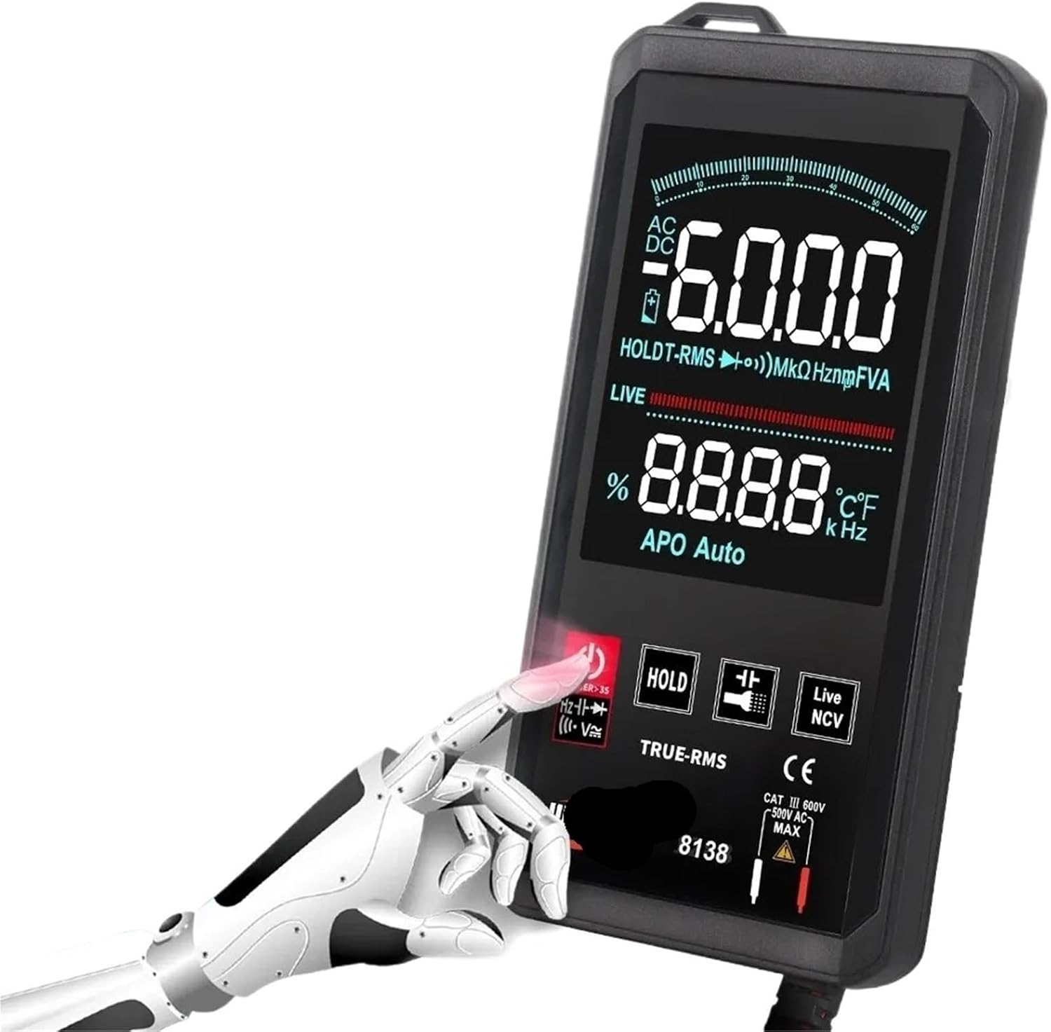
Figure 2.1: WinAPEX ET8136 Digital Multimeter with red and black test leads.
Key Features:
- True RMS measurement
- Automatic measurement of AC/DC voltage and resistance
- 6000 counts display
- Live wire detection (LIVE)
- Non-Contact Voltage (NCV) detection
- Frequency, Capacitance, Diode, and Continuity testing
- Data Hold function
- Large LCD display with backlight
- Built-in flashlight
3. Setup
3.1 Unpacking and Inspection
Carefully unpack the multimeter and check for any signs of damage. Ensure all components are present.

Figure 3.1: Package contents typically include the multimeter, test leads, user manual, and a storage pouch.
3.2 Battery Installation
The ET8136 requires one AAA 1.5V battery (not included). To install:
- Locate the battery compartment cover on the back of the multimeter.
- Use a screwdriver to open the battery compartment.
- Insert the AAA 1.5V battery, observing the correct polarity (+ and -).
- Replace the battery compartment cover and secure it with the screw.
3.3 Connecting Test Leads
Connect the test leads to the multimeter as follows:
- Insert the red test lead into the VΩHz input jack.
- Insert the black test lead into the COM (common) input jack.
Ensure the connections are firm before use.
4. Operating Instructions
Press the power button (POWER) to turn the multimeter ON or OFF.
4.1 Automatic Measurement (Smart Mode)
The ET8136 features an intelligent scanning mode that automatically recognizes and measures AC/DC voltage and resistance. Simply connect the test leads to the circuit or component, and the meter will display the appropriate reading.
4.2 Manual Function Selection
While the multimeter is in automatic mode, you can manually switch to other functions by pressing the FUNC button (often labeled with a symbol like 'HOLD' or 'SELECT' depending on the specific model's button layout, but the description implies a function selection capability beyond auto-ranging).
4.2.1 DC Voltage Measurement
- Connect the red test lead to the positive (+) point and the black test lead to the negative (-) point of the DC circuit.
- The meter will automatically detect DC voltage and display the reading.
4.2.2 AC Voltage Measurement
- Connect the test leads across the AC voltage source.
- The meter will automatically detect AC voltage and display the reading, including frequency on the secondary display.
4.2.3 Resistance Measurement
- Ensure the circuit is de-energized before measuring resistance.
- Connect the test leads across the component to be measured.
- The meter will automatically detect resistance and display the reading in Ohms (Ω).
4.2.4 Capacitance Measurement
- Ensure the capacitor is fully discharged before measurement.
- Connect the test leads across the capacitor terminals.
- The meter will display the capacitance value in Farads (F).
4.2.5 Diode Test
- Connect the red test lead to the anode and the black test lead to the cathode of the diode.
- The meter will display the forward voltage drop. Reverse the leads to check for open circuit.
4.2.6 Continuity Test
- Connect the test leads across the circuit or component.
- A continuous beep indicates a good connection (low resistance).
4.2.7 Non-Contact Voltage (NCV) Detection
- Press the NCV button.
- Move the top of the multimeter close to the wire or outlet.
- The meter will indicate the presence of AC voltage with an audible beep and/or visual indicator.
4.2.8 Live Wire Judgment (LIVE)
- Press the LIVE button.
- Insert the red test lead into the socket or touch the wire to be tested.
- The meter will indicate if the wire is live.
4.3 Data Hold Function
Press the HOLD button to freeze the current reading on the display. Press it again to release the hold function.
4.4 Backlight and Flashlight
The multimeter features a large screen LCD display with a backlight and an ultra-high brightness flashlight. These functions are designed to operate effectively even at low battery levels (e.g., 2.3V).
5. Maintenance
5.1 Cleaning
Wipe the multimeter casing with a damp cloth and mild detergent. Do not use abrasive cleaners or solvents. Ensure the device is off and test leads are disconnected before cleaning.
5.2 Battery Replacement
When the low battery indicator appears on the display, replace the AAA 1.5V battery promptly to ensure accurate measurements. Refer to Section 3.2 for battery installation instructions.
5.3 Storage
If the multimeter will not be used for an extended period, remove the battery to prevent leakage. Store the device in a cool, dry place, away from direct sunlight and extreme temperatures.
6. Troubleshooting
- No Display/Power On:
- Check if the battery is installed correctly and has sufficient charge. Replace if necessary.
- Ensure the power button is pressed firmly. - Inaccurate Readings:
- Verify that the test leads are properly connected and not damaged.
- Ensure the correct measurement function is selected (if not using auto-mode).
- Check for external interference or poor contact with the test points.
- Replace the battery if it is low. - Overload Indication (OL):
- This indicates that the measured value exceeds the meter's range. Disconnect immediately to prevent damage.
- Ensure you are not exceeding the maximum input voltage or current ratings.
7. Specifications
| Parameter | Value |
|---|---|
| Display Type | Digital Display, 6000 Counts |
| AC Voltage Range | Up to 750V |
| DC Voltage Range | Up to 1000V |
| Resistance Range | Up to 6 MΩ |
| Capacitance Range | Up to 60 mF |
| Power Supply | 1 x AAA 1.5V Battery (not included) |
| Dimensions | 133 x 67 x 12 mm |
| Weight | 50 Grams (excluding battery) |
| Safety Rating | CE Certified |
8. Warranty and Support
For warranty information or technical support, please refer to the documentation provided with your purchase or contact the retailer. Keep your purchase receipt as proof of purchase.


