
Srliya 9808+
Srliya 9808+ Digital Multimeter User Manual
Multifunctional Electrical Tester for AC/DC Voltage, Current, Capacitance, and More
1. Introduction
The Srliya 9808+ Digital Multimeter is a stable and high-performance measuring instrument designed for various electrical tests. It is an ideal tool for laboratories, factories, and home use, capable of measuring DCV, ACV, DCA, ACA, resistance, capacitance, inductance, temperature, and frequency. Additionally, it supports diode, transistor, and continuity tests. Featuring a large LCD screen with backlight, it ensures clear readability and ease of use in diverse environments.
2. Safety Information
WARNING: Please read all instructions carefully before using this device. Failure to follow safety guidelines may result in electric shock, fire, or damage to the meter or the equipment under test.
- Always ensure the test leads are properly connected and the function switch is set to the correct range before making any measurements.
- Do not attempt to measure voltages or currents exceeding the maximum specified limits for the device.
- Exercise extreme caution when working with live circuits. Avoid contact with bare wires or terminals.
- Never operate the multimeter if it appears damaged or if the battery cover is not securely closed.
- Replace batteries immediately when the low battery indicator appears to ensure accurate readings.
- Adhere to all local and national safety codes.
3. Package Contents
Verify that all items listed below are present in your package:
- 1 x Srliya 9808+ Digital Multimeter (Batteries Not Included)
- 2 x Test Leads (Red and Black)
- 1 x Temperature Probe
- 1 x User Manual
4. Product Overview
The Srliya 9808+ Digital Multimeter features a robust design with a clear LCD display and an intuitive rotary switch for function selection.

Figure 4.1: Front view of the Srliya 9808+ Digital Multimeter with its kickstand extended.
4.1. Components
- LCD Display: Shows measurement readings, units, and function indicators.
- Function Buttons: Include POWER/APO, HOLD/B/L (Backlight), SELECT, REL/MAX/MIN.
- Rotary Switch: Used to select the desired measurement function and range.
- Input Jacks:
- COM Jack: Common terminal for all measurements (black test lead).
- VΩHz Jack: Input for voltage, resistance, frequency, capacitance, diode, and continuity measurements (red test lead).
- mAμA Jack: Input for current measurements up to 200mA (red test lead).
- 20A Jack: Input for high current measurements up to 20A (red test lead).
- Transistor Test Socket: For hFE measurements of NPN/PNP transistors.
- Kickstand: For convenient hands-free operation.
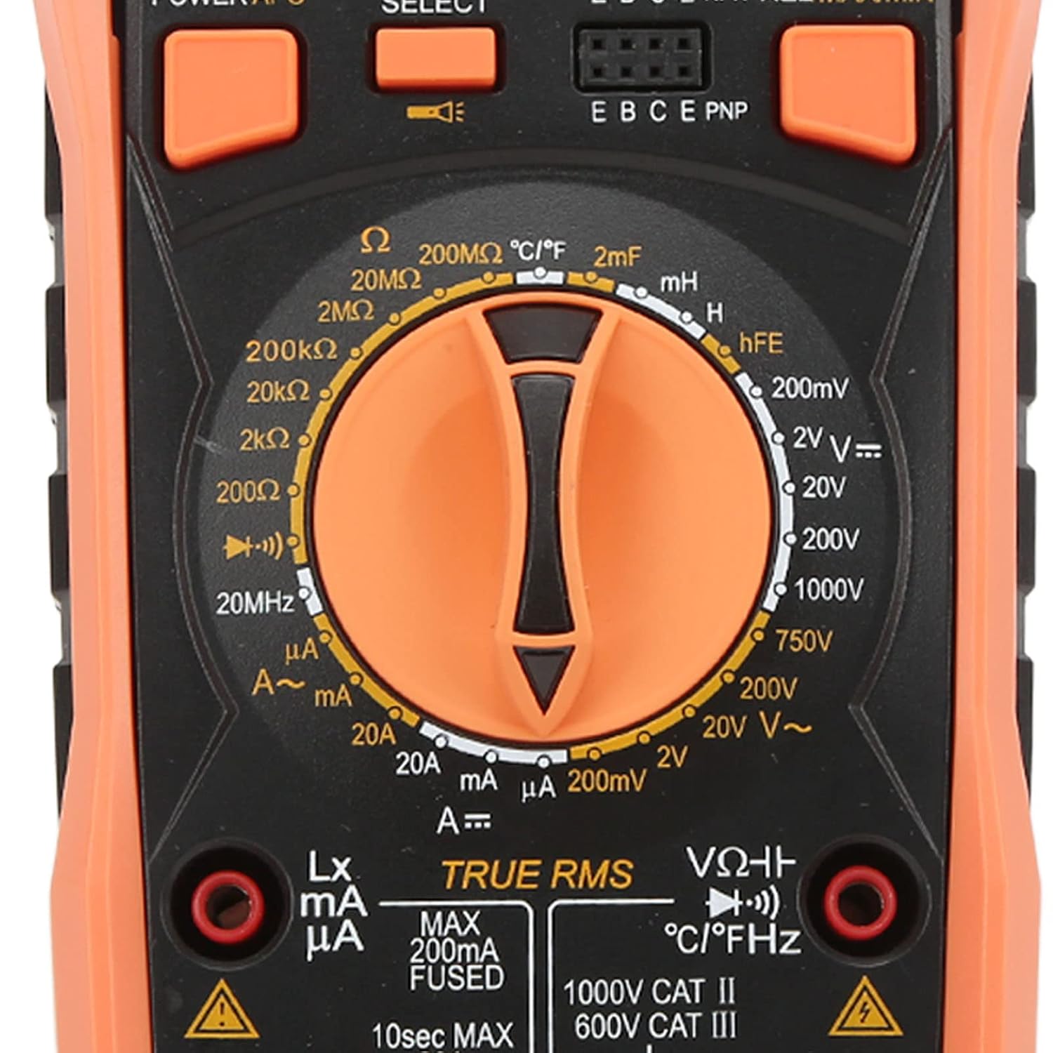
Figure 4.2: Close-up view of the rotary switch, display, and function buttons.

Figure 4.3: Rear view of the multimeter, illustrating the battery compartment and kickstand.
5. Setup
5.1. Battery Installation
The multimeter requires 4 x AAA batteries (not included) for operation.
- Ensure the multimeter is powered off.
- Locate the battery compartment on the back of the device (refer to Figure 4.3).
- Unscrew the retaining screw and remove the battery cover.
- Insert 4 AAA batteries, observing the correct polarity (+/-) as indicated inside the compartment.
- Replace the battery cover and secure it with the screw.
5.2. Connecting Test Leads
Always connect the black test lead to the COM jack. Connect the red test lead to the appropriate input jack based on the desired measurement:
- For Voltage, Resistance, Capacitance, Frequency, Diode, and Continuity: Connect the red lead to the VΩHz jack.
- For Current (up to 200mA): Connect the red lead to the mAμA jack.
- For High Current (up to 20A): Connect the red lead to the 20A jack.
6. Operating Instructions
6.1. Power On/Off and Backlight
- Press the POWER/APO button to turn the multimeter on.
- Press and hold the POWER/APO button to turn the multimeter off.
- Press the HOLD/B/L button briefly to toggle the backlight on or off.
- The multimeter features an Auto Power Off (APO) function to conserve battery life. It will automatically power off after a period of inactivity.
6.2. Measurement Functions
Rotate the function switch to the desired measurement mode. Use the SELECT button to cycle through sub-functions if available (e.g., AC/DC for voltage/current, different units for temperature).
6.2.1. DC Voltage Measurement (V—)
- Connect the black test lead to the COM jack and the red test lead to the VΩHz jack.
- Set the rotary switch to the V— position.
- Connect the test leads in parallel to the DC voltage source or component to be measured.
- Read the voltage value on the LCD display.
6.2.2. AC Voltage Measurement (V∼)
- Connect the black test lead to the COM jack and the red test lead to the VΩHz jack.
- Set the rotary switch to the V∼ position.
- Connect the test leads in parallel to the AC voltage source or component to be measured.
- Read the voltage value on the LCD display.
6.2.3. DC Current Measurement (A—)
- Connect the black test lead to the COM jack.
- For currents up to 200mA, connect the red test lead to the mAμA jack. For currents up to 20A, connect the red test lead to the 20A jack.
- Set the rotary switch to the appropriate A— range (μA, mA, or A).
- Disconnect power to the circuit. Open the circuit where the current is to be measured and connect the multimeter in series.
- Apply power to the circuit and read the current value on the LCD display.
6.2.4. AC Current Measurement (A∼)
- Follow the same connection procedure as for DC Current Measurement.
- Set the rotary switch to the appropriate A∼ range (μA, mA, or A).
- Disconnect power to the circuit. Open the circuit where the current is to be measured and connect the multimeter in series.
- Apply power to the circuit and read the current value on the LCD display.
6.2.5. Resistance Measurement (Ω)
- Connect the black test lead to the COM jack and the red test lead to the VΩHz jack.
- Set the rotary switch to the Ω position.
- Ensure the circuit or component under test is de-energized.
- Connect the test leads across the component to be measured.
- Read the resistance value on the LCD display.
6.2.6. Capacitance Measurement (F)
- Connect the black test lead to the COM jack and the red test lead to the VΩHz jack.
- Set the rotary switch to the F position.
- Ensure the capacitor is fully discharged before connecting the test leads.
- Connect the test leads across the capacitor terminals.
- Read the capacitance value on the LCD display.
6.2.7. Inductance Measurement (H)
- Connect the black test lead to the COM jack and the red test lead to the VΩHz jack.
- Set the rotary switch to the H position.
- Connect the test leads across the inductor terminals.
- Read the inductance value on the LCD display.
6.2.8. Frequency Measurement (Hz)
- Connect the black test lead to the COM jack and the red test lead to the VΩHz jack.
- Set the rotary switch to the Hz position.
- Connect the test leads in parallel to the signal source.
- Read the frequency value on the LCD display.
6.2.9. Temperature Measurement (℃/℉)
- Connect the temperature probe to the VΩHz and COM jacks, observing polarity.
- Set the rotary switch to the ℃/℉ position.
- Place the tip of the temperature probe on or near the object whose temperature is to be measured.
- Read the temperature value on the LCD display. Use the SELECT button to switch between Celsius (℃) and Fahrenheit (℉).
6.2.10. Diode Test (→|—)
- Connect the black test lead to the COM jack and the red test lead to the VΩHz jack.
- Set the rotary switch to the →|— position.
- Connect the red test lead to the anode and the black test lead to the cathode of the diode.
- The display will show the forward voltage drop. Reverse the leads; the display should show 'OL' for an open circuit if the diode is good.
6.2.11. Transistor Test (hFE)
- Set the rotary switch to the hFE position.
- Identify if the transistor is NPN or PNP.
- Insert the transistor leads (Emitter, Base, Collector) into the corresponding holes in the transistor test socket.
- Read the hFE value on the LCD display.
6.2.12. Continuity Test (“““)
- Connect the black test lead to the COM jack and the red test lead to the VΩHz jack.
- Set the rotary switch to the “““ position.
- Connect the test leads across the circuit or component.
- If continuity exists (resistance below a certain threshold), the buzzer will sound, and the display will show the resistance value.
6.3. Special Functions
- Data Holding (HOLD): Press the HOLD/B/L button briefly during a measurement to freeze the current reading on the display. Press again to release.
- Relative Measurement (REL): Press the REL/MAX/MIN button to store the current reading as a reference value. Subsequent measurements will be displayed as a difference from this reference. Press again to exit.
- Maximum/Minimum Value (MAX/MIN): Press the REL/MAX/MIN button (after REL, or if REL is not active) to enter MAX/MIN mode. The meter will display the maximum or minimum value recorded since entering this mode. Press again to cycle between MAX, MIN, and current reading. Press and hold to exit.
- TRUE RMS: This multimeter features TRUE RMS measurement for AC voltage and current, providing accurate readings for non-sinusoidal waveforms.
7. Specifications
| Function | Range | Accuracy |
|---|---|---|
| DC Voltage | 200mV, 2V/20V/200V, 1000V | ±(0.5%+5), ±(0.5%+3), ±(1.0%+10) |
| AC Voltage | 200mV, 2V/20V/200V, 750V | ±(1.0%+5), ±(0.8%+5), ±(1.2%+10) |
| DC Current | 200μA/2mA/20mA/200mA, 20A | ±(1.2%+8), ±(2.0%+5) |
| AC Current | 200μA/2mA/20mA/200mA, 20A | ±(1.5%+15), ±(3.0%+10) |
| Resistance | 200Ω, 2kΩ/20kΩ/200kΩ/2MΩ, 20MΩ, 200MΩ | ±(0.8%+5), ±(0.8%+3), ±(1.0%+25), ±(5.0%+30) |
| Inductance | 2mH/20mH/200mH, 2H/20H | ±(2.5%+30), ±(5.0%+20) |
| Capacitance | 20nF/200nF/2μF/20μF, 200μF/20mF | ±(3.5%+20), ±(5.0%+10) |
| Frequency | 10Hz to 20MHz | ±(1.0%+10) |
| Temperature | -20℃ to 1000℃ (-4℉ to 1832℉) | <400℃ ±(1.0%+5), ≥400℃ ±(1.5%+15) |
7.1. General Specifications
- Display: 1999 Counts LCD, 65 x 40mm
- Input Impedance: 10MΩ
- Sampling Rate: 3 Times/s
- AC Frequency Response: (40-1000)Hz
- Measurement Method: Manual Range
- Battery: 4 x AAA Batteries (Not Included)
- Features: Diode and Transistor Test, Continuity Buzzer, Low Battery Indication, TRUE RMS, Data Holding, Auto Power off, Backlight, Maximum/Minimum Value.
- Dimensions: Approximately 8.27 x 5.51 x 2.76 inches
- Weight: Approximately 1.29 Pounds (584g)
8. Maintenance
8.1. Cleaning
To clean the multimeter, wipe the case with a damp cloth and a mild detergent. Do not use abrasives or solvents. Ensure the device is powered off and test leads are disconnected before cleaning.
8.2. Battery Replacement
When the low battery indicator appears on the display, replace the batteries promptly to ensure accurate measurements. Refer to Section 5.1 for battery installation instructions.
8.3. Fuse Replacement
If the current measurement function fails, the fuse may need replacement. This device uses specific fuses for protection. Refer to the specifications for the correct fuse type and rating. Fuse replacement should only be performed by qualified personnel.
9. Troubleshooting
- No Display or Faint Display: Check battery installation and ensure batteries are not depleted. Replace if necessary.
- Incorrect Readings: Verify that the function switch is set to the correct measurement mode and range. Ensure test leads are properly connected and making good contact with the circuit. Check for damaged test leads.
- No Current Measurement: Check if the fuse for the current input is blown. Replace if needed (refer to Section 8.3). Ensure the multimeter is connected in series with the circuit.
- 'OL' (Overload) Display: The measured value exceeds the selected range. Switch to a higher range or verify the circuit is within the meter's capabilities.
10. Support
For further assistance or technical support regarding your Srliya 9808+ Digital Multimeter, please refer to the manufacturer's official website or contact their customer service department. Keep your purchase receipt and model number handy for efficient service.
Ask a question about this manual
Ask about setup, troubleshooting, compatibility, parts, safety, or missing instructions. Manuals+ will review the question and use this page’s manual context to help answer it.